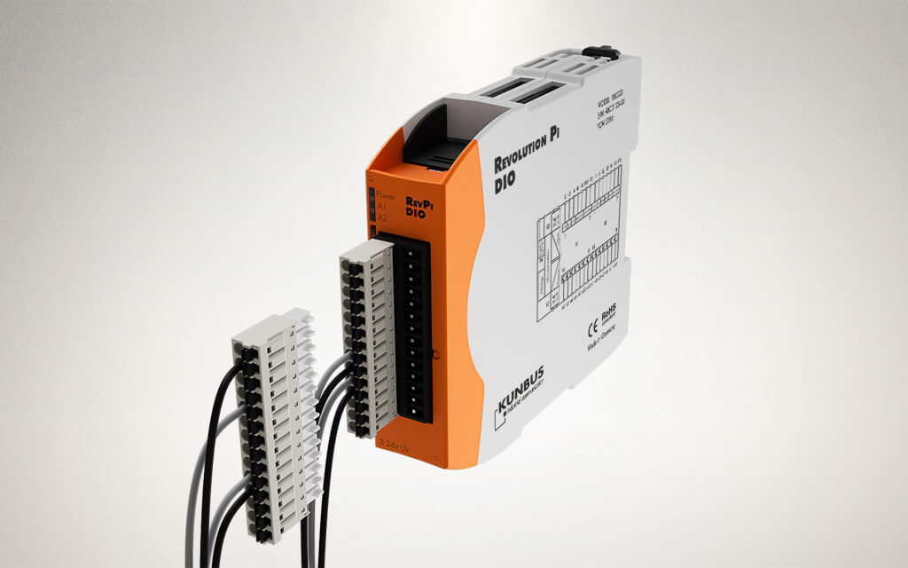
The last two weeks we’ve explained RevPi Core. Today we will reveal all the details about our digital I/O modules.
I/O Module Versions
There are three versions of our digital I/O module available. All of them have the same 28 pin connector on the front side (2 rows of 14 male pins – suitable female connectors with spring clip contacts for up to 1.5 mm² flex wire included):
- Standard version RevPi DIO has 14 digital inputs and 14 digital outputs
- Special version RevPi DI has 16 digital inputs
- Special version RevPi DO has 16 digital outputs
All versions have galvanic separation between PiBridge logic circuit and inputs resp. outputs (600 VRMS isolation voltage). The RevPi DIO version has additionally galvanic separation between inputs and outputs. All versions are protected against interference according to EN61131-2 requirements and may be operated between -40°C to 55°C ambient temperature with up to 80% rel. humidity.*
Power Supply
As a result of galvanic separation of the PiBridge logic circuit it needs its own power supply connector which is also providing a mandatory functional earth connection (4 pin connector with screw terminals). This power supply section works with 10.2 V up to 28.8 V input voltage and draws a maximum of 50 mA current (at 24 V – 100 mA at 12 V) used for an STM32F205 MPU. This MPU is controlling the data exchange over the PiBridge and exchanges data with input and output lines using galvanic separated SPI lines. This power supply circuit does bypass a loss of power at its input of up to 77 ms (at 24 V; reduced to 8 ms at 12 V).
For a perfect galvanic separation the input and output circuits should get their own supply voltages using an additional 4 pin connector with screw terminals. These input and output power supplies should reference to the according GND level of sensors (contacts, switches, etc.) and actuators (relays etc.). Their voltage has to be between 10.2 V and 28.8 V. Inputs only have norm compliant thresholds for 24 V supply voltage. Current consumption for input supply is about 10 mA maximum. For the outputs the power consumption depends heavily on connected loads which can be up to 500 mA per channel (which adds up to a maximum of 8 A current consumption for the DO variant).
All power supply inputs are protected against reverse polarity, over voltages and transient voltage or current interference according to requirements of EN61131-2.
Functionality
Switching status of inputs and outputs are cyclically exchanged via PiBridge with the RevPi Core’s central processing image using the PiControl driver. Additionally to switching status the possible error conditions (diagnostic data) and configuration data is also cyclically transmitted.
During startup a module detection identifies all modules and their physical position left or right of RevPi Core. After this detection phase the modules get their non-cyclic configuration data. Then the system changes into process data transfer phase in which the RS485 channel of PiBridge and a time optimized protocol is used for data exchange.
Overall cycle time is guaranteed 5 ms for a system having 1 DIO and 2 RevPi Gate modules or 10 ms for a system having 3 DIO and 2 RevPi Gate modules. This is too slow to effectively use the outputs for PWM control or the inputs for encoder signals which need to be picked up with more than 100 Hz sample frequency. Such tasks can be done with RevPi MOT modules, a future product.
Inputs
The DC inputs have a voltage threshold which for 24 V supply voltage is compliant to EN61131-2 Type 1 and Type 3 input definitions. Input current is clamped at a maximum of 2.4 mA. This norm is not defined for 12 V inputs therefore we cannot test for any compliance. But thresholds are reasonably reduced with supply voltage. If voltage supply drops under 9 V, an alarm is sent to RevPi Core. This can be used as indication of unreliable input values which are no longer compliant to norm for a 24 V digital input.
There is an adjustable low-pass filtering to prevent input signal bouncing. This filter can only be applied to all inputs or none. The filter only propagates input values which are stable for at least 25 µs, 750µs or 3 ms (value is part of configuration). All inputs are protected against ESD, bursts and surges according to demands of EN61131-2.
Outputs
Each output can be configured separately as high side switch with max. 500 mA current load or push-pull output with a maximum load of 100 mA. Independently from their output mode each single channel is protected against over current and is short circuit safe. A hardware watchdog circuit is monitoring the SPI data exchange between MPU and output circuit. If there is no SPI traffic, outputs are forced to 0 (safe state). Outputs are also forced to their safe state if output power supply drops low or the output circuit reached an over-temperature condition. Such error conditions as well as short circuit state of each channel is cyclically transmitted to RevPi Core.
Each output can additionally be configured to detect open load conditions when in high side switch mode and send an alarm to RevPi Core. Just like the inputs all outputs are protected against ESD, bursts and surges according to demands of EN61131-2.
*Temperature range depends on total output current. Upon completion of the tests, the results will be published.

