RevPi Documentation
Welcome to the RevPi Documentation Portal! Quickly and easily find all the important information and resources for Revolution Pi.
If you have any questions or technical problems, you can find more information in the REVOLUTION PI FORUM or contact support@kunbus.com.
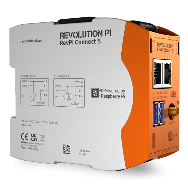
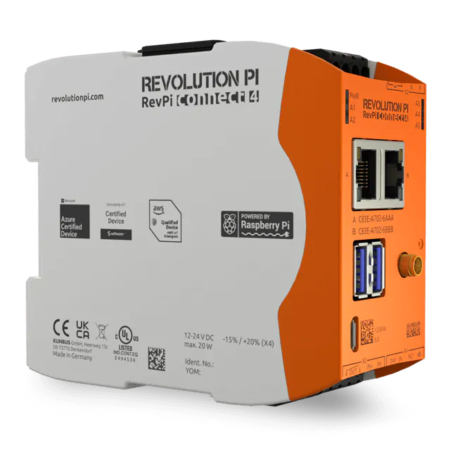
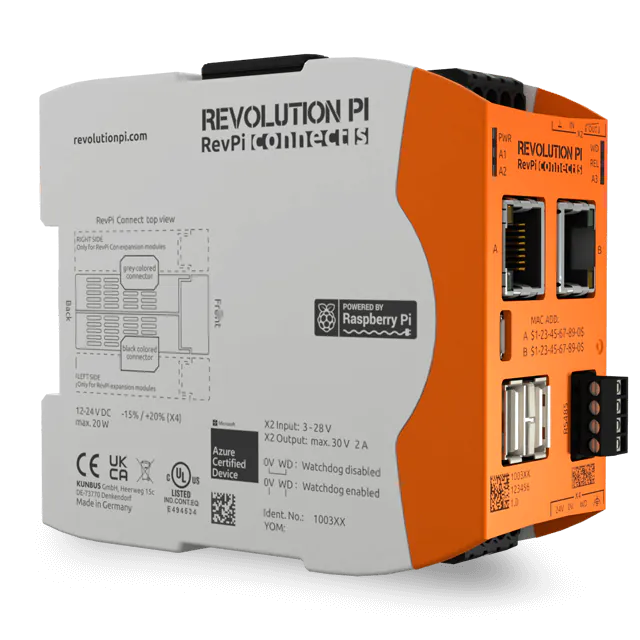
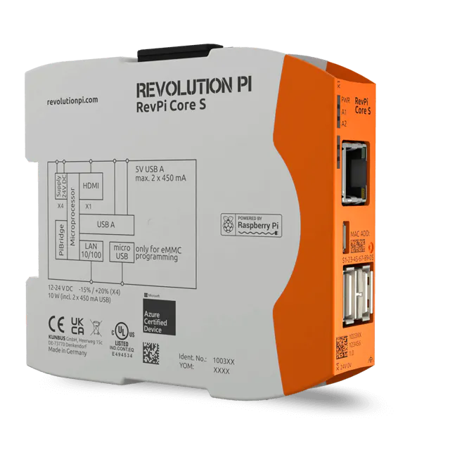
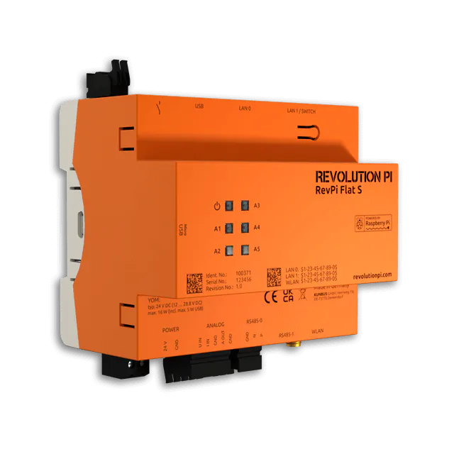
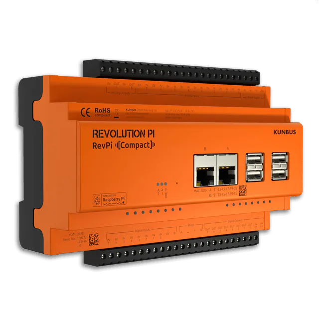
RevPi Base Modules
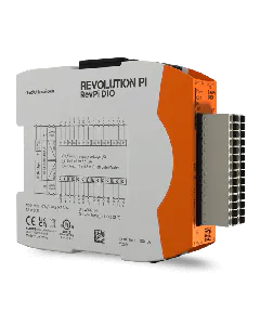
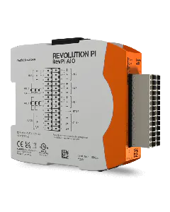
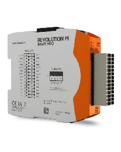
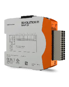
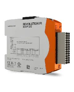
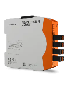
RevPi Expansion Modules
RevPi Con Modules
RevPi Gateways
🔶 Download Manual RevPi Gateway PROFINET IRT
🔶 Download Manual RevPi Gateway Ethernet/IP
🔶 Download Manual RevPi Gateway EtherCAT
🔶 Download Manual RevPi Gateway PROFIBUS