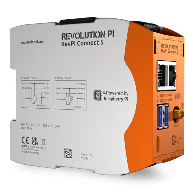
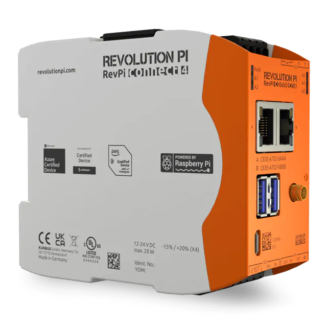
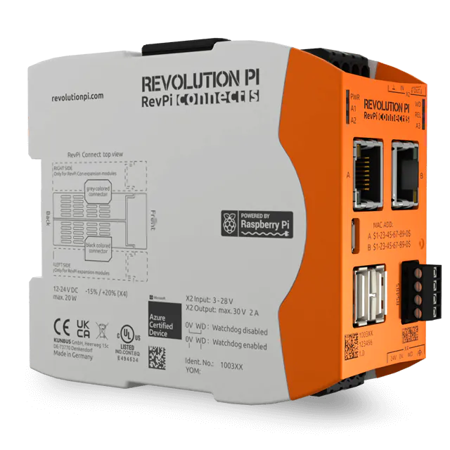
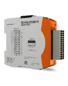
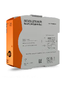
You can use PiCtory to configure your RevPi MIO. In this chapter we will describe in more detail the setting values of the “Value Editor” for the analog outputs.
Your RevPi MIO has four digital connections, which you can use either as an input or output.
To ensure your configuration works it’s important that your devices are connected to the right output pins.
Requirements:
- You have installed a web browser on your PC (e.g. Chrome or Firefox).
- Your RevPi Connect and RevPi MIO are connected via the PiBridge.
- Your RevPi Connect is in your network.
- Start PiCtory.
- Select the RevPi Connect from the Device Catalog.
- Drag and drop the RevPi Connect on to the Configuration Board.
- Open the “I/O Devices” folder in the Device Catalog.
- Select the RevPi MIO.
- Drag and drop the RevPi MIO into the empty slot on the Configuration Board, to the left of the RevPi Connect.
- Define the basic settings for your adapters in the “Device Data” area. This entry is optional. If you use a lot of devices and wish to process the data in another program later, then this entry can be very helpful.
- Configure the outputs in the “Value Editor”. You will find the detailed setting values and descriptions of how to set the individual operating modes at the end of this chapter.
- Click on “File>Save”. This saves your configuration.
- Click on “Tools>Reset Driver”. This activates the changes for the adapter.
- Do you want to continue using the settings in logiCAD3, Python or C? Then click on “File>Export”.
A window opens. Here you can specify the format of the file and enter the file name.
Setting and Configuring Operating Mode
You can use the digital inputs and outputs in either one of the following six operating modes.
Note: If you have configured an analog input as a digital input, then you can use this input only to detect the threshold value.
Using Digital Input for PWM Measurement
Frequency and duty cycle are measured in the PWM operating mode. The frequency is output in Hz and the duty cycle as a percentage with one decimal place (0-999→ 0.0-100.0 %).
If no edge is detected for a length of over 10 seconds, the value 0(no edge detected) is entered for duty cycle and frequency.
In the following example we will configure the first digital connection to use for PWM measurements. To do this you will need to set the following values in the “Value Editor” in PiCtory:
IO_Mode_1 = PWM Input
PWM Dutycycle_1 = Set the duty cycle here.
→ In the field Fpwm/PulseCount_1 you can then read the value that arrives at the device.
Using Digital Input for Pulse Measurement
Pulse measurements up to a length of 65535 ms are possible. It is always the measurement from the last complete pulse that is transmitted.
The physical pulse duration is also measured and the pulses counted. The period PulseLength_x is started each time a pulse is detected (rising edge).
In the following example we will configure the first digital connection to use for pulse measurements. To do this you will need to set the following values in the “Value Editor” in PiCtory:
IO_Mode = PulseIn
->In the field DutyCycle_PulseLength_1- you can read the measured pulse length in milliseconds.
->In the field Fpwm_PulseCount_1- you can see the number of registered pulses.
Using Digital Input for Level Detection
In the following example we will configure the first digital connection to use for level detection. To do this you will need to set the following values in the “Value Editor” in PiCtory:
IO_Mode_1 = Input
->In the field DigitalInput_1 you can read the level that is present at the input.
Using Digital Output for PWM Output
The four outputs are divided across 3 independent timers. GPO1 and GPO2 share a timer; GPO3 and GPO4 each have their own timer. As a result, 3 frequencies can be set. You will need to preconfigure the PWM frequency in PiCtory and restart the driver in order to adopt the changes. You can set the duty cycle (as a percentage with one decimal place) for each GPO individually (0-999→ 0.0-100.0 %).
The possible frequencies follow the formula f=(2*fp)/(1000*(x+1)). fp is 30 MHz for GPO1&2 and 60 MHz for GPO3&4.
This results in maximum frequencies of 60 kHz (GPO1&2) and 120 kHz (GPO3&4). When x_max=65535, minimum frequencies of 2 Hz (GPO1&2) and 1 Hz (GPO3&4) are the result.
In the following example we will configure the first digital connection to use to output the PWM. To do this you will need to set the following values in the “Value Editor” in PiCtory:
IO_Mode_1 = Output PWM.
FpwmOut_12 = Set the frequency of your PWM signal here.
PWM Dutycycle_1 = Set the duty cycle here.
Using Digital Output for Pulse Output
On each GPO you can generate a pulse with a length of 1 ms to 65535 ms.
The pulse can be generated once or regularly in Retrigger Mode.
One-off pulse:
If the value DigitalOutput_1 (in the process image) is set to 1, a pulse with the configured length Pulselength_1 is started. The next pulse can only be started once the current pulse is complete.
Retrigger Mode: If the value DigitalOutput_1 (in the process image) is set to 1, a pulse with the configured length Pulselength_1 is started. Current pulses can be restarted in retrigger mode.
Note: Before a new pulse can be started, the value DigitalOutput_x must be at 0 for at least one PiBridge cycle.
In the following example we will configure the first digital connection to use to output the pulse. To do this you will need to set the following values in the “Value Editor” in PiCtory:
IO_Mode_1 = Output Pulse
PulseMode = 1, in order to activate retrigger mode.
Dutycycle_Pulselength_1 = Set the pulse length for the connection here.
DigitalOutput_1 = 1, to start the pulse.
ATTENTION: Before you can start a new pulse, the field DigitalOutput_1 must be set to 0 for at least one PiBridge cycle.
Using Digital Output for Level Output
In the following example we will configure the first digital connection to use to output the level. To do this you will need to set the following values in the “Value Editor” in PiCtory:
IO_Mode_1 = Output
DigitalOutput_1 = Here you can set the digital output to low (0) or high (1).
List of the Setting Values for the Digital Inputs and Outputs in PiCtory
This is a summary of all the setting values for the digital inputs and outputs.
PiCtory setting |
Values |
Function |
---|---|---|
DigitalInput_1-5 |
0: low 1: high |
The value indicates which level is present at the input. |
Dutycycle_Pulselength_1-4 |
0-65535 |
This value indicates the measured duty cycle or the measured pulse length, depending on which mode is set. |
Fpwm/PulseCount_1-4 |
0-2000 |
This value indicates the measured frequency or registered pulses, depending on which mode is set. |
DigitalOutput_1-4 |
0: low 1: high |
Here you can set the individual digital outputs to high or low. |
PWM Dutycycle_1-4 |
0-999 |
Here you can set the duty cycle* for the individual digital outputs. *The duty cycle indicates the ratio between pulse duration and period duration for a periodic sequence of pulses. |
Encoder Mode |
0 = No encoder |
If you set the value 1 here, you can use GPIO3 and GPIO4 as a quad encoder input. GPIO1 and GPIO2 can continue to be used as an output with all modes or as an input (no PWM, no pulse). |
IO_Mode_1-4 |
0 = Input 1 = PulseInput 5 = Output-Pwm |
Here you can define the operating mode for the respective digital input or output. |
PulseMode |
0 = Single 1 = Retrigger |
Here you can activate retrigger mode. |
FPWMOUT_12, 3,4 |
0-65535 |
12= PWM frequency for digital outputs 1 and 2. These two connections always share the same PWM frequency. Connections 3 and 4 can be configured separately. |
PulseLength_1-4 |
0-65535 |
Pulse length on the respective digital output. |