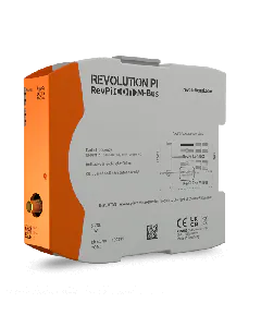
RevPi Gate PROFIBUS

To configure the gateway component, you have to perform the appropriate settings with the configuration software of your PROFIBUS Master (class 1).

The PROFIBUS gateway component is created as a so-called “modular DP-V0 Slave”. This means that the process data exchanged between the gateways can be structured application-specific on the profibus side.

The gateway component is equipped for this with virtual slots (installation positions). PROFIBUS controllers use these slots to address selected process data. Each slot can contain one module. Within these modules is the process data to be exchanged. Hence, you have the possibility of aggregating associated process data in one slot. This means, for example, that you can poll a compact process mapping of associated states.

If you do not want to use a slot, you can mark it with an empty module. You do not have to perform any further settings on the empty module.

The process data is accessed between the gateway components in separate memory areas for input and output data. The sequence order in which the access takes place depends on the configuration of the modules.

The data of the modules is stored directly in succession in the memory area for the data exchange between gateways (see example further below).

Info! The gateway component does not support any extended diagnosis data.

Byte order:

The bytes are transferred to the controller in Big Endian Format.

Module Configuration

A maximum of 64 slots, each with 244 bytes for input and output data, is available for the module configuration. The modules are preset in the GSD and cannot be changed.

The following modules are available for loading the Slots:


Module number Module type Size[Bytes/Words] Access
0 Empty module 0
1 Output 1 Byte
2 Output 2 Byte
3 Output 4 Byte
4 Output 8 Byte
5 Output 16 Byte
6 Input 1 Byte
7 Input 2 Byte
8 Input 4 Byte
9 Input 8 Byte
10 Input 16 Byte
11 Input/Output 1 Byte
12 Input/Output 2 Byte
13 Input/Output 4 Byte
14 Input/Output 8 Byte
15 Input/Output 16 Byte
16 Output 1 Word
17 Output 2 Word
18 Output 4 Word
19 Output 8 Word
20 Output 16 Word
21 Input 1 Word
22 Input 2 Word
23 Input 4 Word
24 Input 8 Word
25 Input 16 Word
26 Input/Output 1 Word
27 Input/Output 2 Word
28 Input/Output 4 Word
29 Input/Output 8 Word
30 Input/Output 16 Word

Example of Module Configuration

The following slots are to be configured:

Slot Module type Size [Bytes/Words] Access Module number
1 Input 1 Byte 6
2 Input 16 Byte 10
3 Output 16 Byte 5
4 Empty module 0 0
5 Input 1 Byte 6
6 Output 8 Byte 4
7 Input 4 Byte 8
8 Input/Output 4 Byte 13
9 Empty module 0 0
10 Input/Output 1 Word 26
11 Output 1 Word 16
12 Input 1 Word 21

The following tables provide the memory maps of the example and are thus used for data exchange with other gateways.

Input data

Offset Byte 0 Byte 1 Byte 2 Byte 3 Byte 4 Byte 5 Byte 6 Byte 7
0x0000 Slot 1 Slot 2 Slot 2 Slot 2 Slot 2 Slot 2 Slot 2 Slot 2
0x0008 Slot 2 Slot 2 Slot 2 Slot 2 Slot 2 Slot 2 Slot 2 Slot 2
0x0010 Slot 2 Slot 5 Slot 7 Slot 7 Slot 7 Slot 7 Slot 8 Slot 8
0x0018 Slot 8 Slot 8 Slot 10 (L)* Slot 10 (H*) Slot 12 (L)* Slot 12 (H*)


Output data

Offset Byte 0 Byte 1 Byte 2 Byte 3 Byte 4 Byte 5 Byte 6 Byte 7
0x0000 Slot 3 Slot 3 Slot 3 Slot 3 Slot 3 Slot 3 Slot 3 Slot 3
0x0008 Slot 3 Slot 3 Slot 3 Slot 3 Slot 3 Slot 3 Slot 3 Slot 3
0x0010 Slot 6 Slot 6 Slot 6 Slot 6 Slot 6 Slot 6 Slot 6 Slot 6
0x0018 Slot 8 Slot 8 Slot 8 Slot 8 Slot 10 (L)* Slot 10 (H)* Slot 11 (L)* Slot 11 (H)*

*(L)=Low Byte, (H)=High Byte