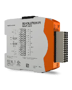
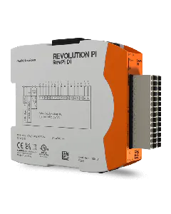
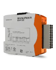
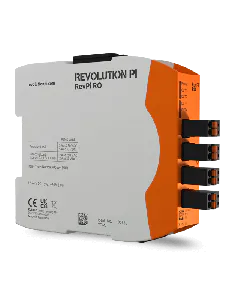
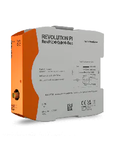
To evaluate a fault status of the RevPi AIO precisely, your user software has to evaluate the status entry in the process image. Status entries are stored there as input values from the PiControl driver. The position (offset) in the process image can be gleaned for example from the offset export in PiCtory or inquired via the symbolic name of the respective status values also with the piTest command line tool. The meaning of each individual bit belonging to the status bytes can be found in the table below:
Bit | Cause | LED signal | Reaction |
Status signals analog outputs | |||
Bit 0 (LSB) | Temperature fault in the output module. The output module has overheated due to being overloaded for a longer period of time (short circuit). | red steady | – |
Bit 1 | Open load fault from the power output. In the “power output” operating mode, the connected circuit is too highly resistive due to, for example, the circuit being interrupted. | red steady | – |
Bit 2 | Internal CRC fault from output module. The fault indicates a hardware defect or serious external interference signal. | red steady | – |
Bit 3 | Range fault: The default value is outside the configurated output range. | red flashes | The output is set to the maximum or minimum permissible value. |
Bit 4 | Reserved for internal purposes | ||
Bit 5 | Supply voltage of the AIO module is below 10.2 V | red steady | The outputs are set to 0 as a safe operation cannot be guaranteed. |
Bit 6 | Supply voltage of the AIO module is over 28.8 V. | red steady | The outputs are set to 0 as a safe operation cannot be guaranteed. |
Bit 7 (MSB) | Time-out in the connection to RevPi Core (e.g. due to a PiBridge error when the PiControl drive programm no longer runs properly). | red steady | The outputs are set to 0. This is the presumable safe state that is also prevalent at the outputs when starting the AIO. |
Status signals analog inputs | |||
Bit 0 (MSB) | Input value is at least 20 mV or 24 µA respectively under the configured input range. | red flashes | – |
Bit 1 | Input value is at least 20 mV or 24 µA respectively over the configured input range. | red flashes | – |
Status signals temperature input | |||
Bit 0 (MSB) | Measured temperature is below -200 °C or a sensor short circuit. | – | – |
Bit 1 | Measured temperature over 850 °C or a sensor is not connected or the power supply is severed respectively. | – | – |