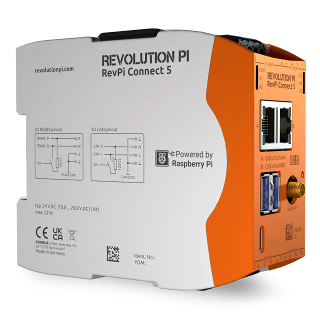
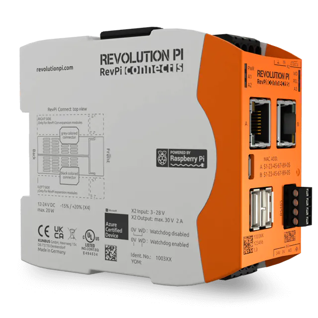
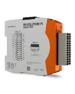
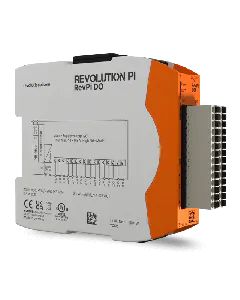
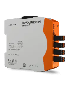
Your RevPi MIO has eight analog inputs. These inputs can be used as a voltage input. Here you can connect sensors such as proximity or level sensors with analog outputs. The maximum common mode voltage per input may be between 0 and 10 V.
To ensure your configuration works it’s important that your devices are connected to the right input pins.
Requirements
- You have installed a web browser on your PC (e.g. Chrome or Firefox).
- Your RevPi Connect and RevPi MIO are connected via the PiBridge.
- Your RevPi Connect is in your network.
- Start PiCtory.
- Select your RevPi base module from the Device Catalog.
- Drag and drop your RevPi base module on to the Configuration Board.
- Open the I/O Devices folder in the Device Catalog.
- Select the RevPi MIO.
- Drag and drop the RevPi MIO into the empty slot, to the left of the RevPi Connect.
- Define the basic settings for your adapters in the Device Data area. This entry is optional. If you use plenty of devices and wish to process the data in another program later, then this entry can be very helpful.
- Configure the outputs in the Value Editor. You will find the detailed setting values and descriptions of how to set the individual operating modes at the end of this chapter.
- Click on File > Save. This saves your configuration.
- Click on Tools > Reset Driver. This activates the changes for the adapter.
- Do you want to continue using the settings in logiCAD3, Python or C? Then click on File > Export.
A window opens. Here you can specify the format of the file and enter the file name.
Setting and Configuring Operating Mode
You can use the analog inputs in either one of the following operating modes.
Using Analog Input for Voltage Measurement
In the following example we will configure the first analog input to use for voltage measurements. To do this, you will need to set the following values in the Value Editor in PiCtory:
AnalogInputMode1 = analog input
→ In the field Analog Input 1 you will see which input voltage is present at the analog input. The value is output in mV.
Using Analog Input for Level Detection
In the following example we will configure the first analog input to use for level detection. To do this, you will need to set the following values in the Value Editor in PiCtory:
AnalogInputMode1 = LogicLevelInput
InputLogicLevelVoltage_1= Required switching threshold in millivolts.
→ In the field AnalogInputLogicLevel_1 you will see whether the switching threshold has been exceeded.
List of the Setting Values for the Analog Inputs in PiCtory
This is a summary of all the setting values for the analog inputs.
Designation |
Values |
Comment |
---|---|---|
AnalogInputMode 1-8 |
Analog input: Connection is used for voltage measurement. LogicLevelInput: Connection is used for level detection. |
Here you can define whether you wish to use the respective connection for level detection or for voltage measurement. |
AnalogInputLogicLevel_1-8 |
o: Switching threshold has not been exceeded. 1: Switching threshold has been exceeded. |
This value indicates whether the switching threshold has been exceeded. |
Analog Input 1-8 |
Logic 0-10000 |
Here you will see which input voltage is present at the respective analog input. The value is output in mV. |
InputLogicLevelVoltage_1-8 |
0-10000 |
Here you can define the switching thresholds for the analog inputs. |
FilterWindowSize |
1-255 |
Filter width of the moving average filter. |