RevPi as Modbus RTU Master
Introduction
The RevPi base module can act as a Modbus RTU Master, enabling you to connect and communicate with various Modbus RTU slaves such as temperature sensors, push-buttons, and motion detectors. This guide walks you through setting up and configuring your RevPi as a Modbus RTU Master for robust industrial communication.
Prerequisites
Hardware Requirements
- RevPi Base Module (eg. RevPi Connect 4)
- Modbus Slave Devices (e.g., sensors, actuators)
- USB-RS485 Converter (if using USB interface)
OR
Built-in RS485 Terminal (on RevPi Connect/Connect 4)
Software Requirements
- A web browser (e.g., Google Chrome or Mozilla Firefox).
Preparation
For USB Connection (RevPi Core or RevPi Connect):
- Connect a USB port of the RevPi base module to the adapter.
- Use a D-Sub 9 socket to connect the adapter to the slave devices.
- Specify the address of the slaves and make a note of it. If necessary, you can find information on this in the manufacturer’s operating instructions.
If you are using several slaves, you have to make sure that each slave has its own address. If 2 or more slaves have the same address, communication errors occur

| Signal | Sub-D Pin |
|---|---|
| RS485- | 1 |
| RS485+ | 2 |
| GND | 5 |
| +5V | 6 |
Some USB-Serial adapters might only have RS485 data signal lines (D+ and D-).

For RS485 Terminal (RevPi Connect/Connect 4):
RevPi Connect models come equipped with an RS485 screw-type terminal for direct connection. The terminal features:
- A (+): Positive RS485 line.
- B (-): Negative RS485 line.
- GND: Ground.
- Functional Earth: Ensures signal integrity.
Ensure correct wiring for robust and cost-effective integration of RS485 devices.
The socket has common A/B line terminals (better marked than D+ and D-) and reference terminals (internal GND and functional earth via 1 MOhm RC network).
Wiring example for RevPi Connect:

Wiring example for RevPi Connect 4

Step 1: Configure Hardware Connections
- Connect the RS485 Network:
Wire the A (+) and B (-) lines from the RevPi RS485 terminal (or USB-RS485 adapter) to the slave devices. - Assign Unique Slave Addresses:
Each slave must have a unique address. Refer to the device’s manual to configure the address.
Note: Duplicate slave addresses will result in communication errors.
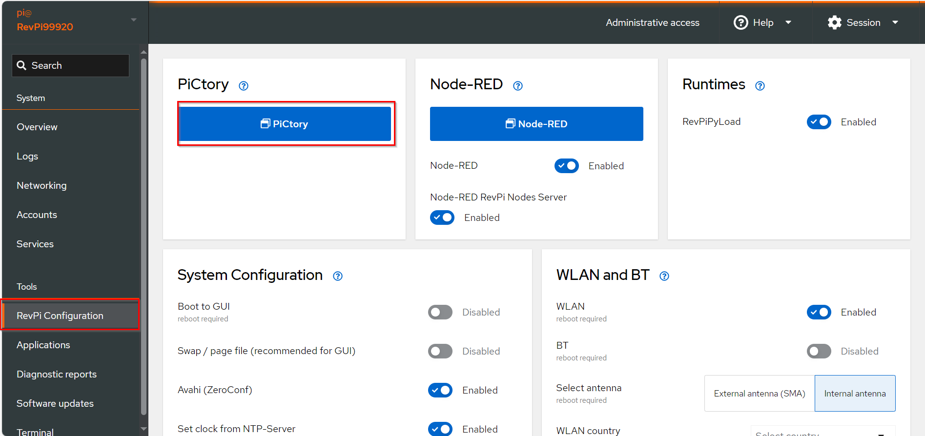
Step 2: Configure Modbus RTU Master in PiCtory

▷ Add Base Module and Add the virtual Modbus RTU Master to your configuration.
▷ Drag the base module from the Device Catalog onto the virtual DIN rail.
▷ Open the folder Virtual Devices in the Device Catalog.
- Drag Modbus RTU Slave to the base module on the virtual DIN rail.
➜ The Modbus RTU Master will now appear in the configuration

- Select the Modbus RTU Master in the configuration.

- Set the following parameters in the Value Editor:
| Parameter | Description |
|----------------------|------------------------------------------------------------------------------------------------------------------------------|
| Input | Configure up to 32 input values (16 bits each). |
| Output | Configure up to 32 output values (16 bits each). |
| device_path | Path to the Linux device file (default:
/dev/ttyRS485). | | baud_rate | Speed of the serial connection (default:19200). | | parity | Parity bit configuration: None, Even (default), Odd. | | data_bits | Number of data bits (default:8). | | stop_bits | Number of stop bits (default:1). |
Configure udev rules for consistent device file paths when using multiple devices of the same type.
▷ Save the configuration and restart the driver to apply the changes.
Step 3: Configure Modbus Commands
-
Open Extended Data:
▷ Right-click on the Modbus RTU Master in the configuration and select Extended Data. -
Add Modbus Commands:
➜ In the input mask, define commands to communicate with the slave:
| Parameter | Description |
|---|---|
| Slave Addr. | Unique address of the slave device (ensure no duplicates). |
| Function Code | Modbus function (e.g., READ_HOLDING_REGISTERS, WRITE_SINGLE_REGISTER). |
| Register Address | Address of the Modbus register or bit (check slave documentation). |
| Quantity | Number of registers/bits to read or write. |
| Action Interval | Interval between commands (in milliseconds). |
| Device Value | Variable name in the RevPi process image for the first word/bit of the command. |

- For devices using 0-based addressing, increment the register address by 1 during configuration.
- Ensure commands do not overlap in the process image.
- Save and Reset:
▷ Click File > Save.
▷ Click Tools > Reset Driver to apply the configuration.
Troubleshooting and Error Codes
If errors occur, check the Modbus_Master_Status register for the error code:
| Error Code | Meaning |
|---|---|
0x10 | Device not found. Check wiring. |
0x11 | Device does not respond. Verify configuration and register address. |
1 | ILLEGAL FUNCTION: Invalid function code. |
2 | ILLEGAL DATA ADDRESS: Invalid or write-protected register address. |
12 | INVALID CRC: Corrupted packet. Check wiring and connections. |
110 | CONNECTION TIMED OUT: Slave did not respond. |
To reset an error, manually write 1 to the Master_Status_Reset or Action_Status_Reset register.
Notes and Best Practices
- Use a higher Action Interval for heavy system loads to prevent communication delays.
- Extend Modbus RTU Master capacity by adding more masters for additional values.
Further Resources