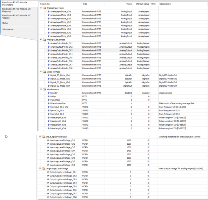
CODESYS helps you to configure your RevPi MIO.
- In the Codesys tree double-click on the RevPi MIO.
- Navigate to the first tab “s Parameters”.

Configuring Digital Inputs and Outputs
The RevPi MIO has a GPIO interface with four connections, which you can use as an option in various operating modes:
- PWM input
- PWM output
- Pulse measurements
- Pulse output
- GPO 24 V level output
- GPI 24 V
The digital inputs and outputs use the same ground as the analog inputs and outputs. For this reason you should use one of the system ground connections on the 28-pin connector strip. If you don”t use this ground, it”s possible that your values will be distorted. If the voltage between the system ground and the ground of the digital inputs and outputs is too high, the protective diode can also be destroyed.
List of the Setting Values for the Digital Inputs and Outputs
|
Parameter |
Values |
Function |
|
DigitalInput_1-4 |
0: low |
The value indicates which level is present at the input. |
|
Dutycycle_Pulselength |
0-65535 |
This value indicates the measured duty cycle or the measured pulse length, depending on which mode is set. |
|
Fpwm/PulseCount |
0-65535 |
This value indicates the measured frequency or registered pulses, depending on which mode is set. |
|
DigitalOutput_1-4 |
0: low |
Here you can set the individual digital outputs to high or low. |
|
PWM Dutycycle_1-4 |
0-1000 |
Here you can set the duty cycle* for the individual digital outputs. *The duty cycle indicates the ratio between pulse duration and period duration for a periodic sequence of pulses. |
|
Encoder Mode |
0 = No encoder GPIO3&4 |
If you set the value 1 here, you can use GPIO3 and GPIO4 as a quad encoder input. GPIO1 and GPIO2 can continue to be used as an output with all modes or as an input (no PWM, no pulse). |
|
IO_Mode_1-4 |
0 = Input 1 = PulseInput 5 = Output-Pwm |
Here you can define the operating mode for the respective digital input or output. |
|
PulseMode |
0 = Single |
Here you can activate retrigger mode. |
|
FPWMOUT_12, 3,4 |
0-65535 |
12= PWM frequency for digital outputs 1 and 2. These two connections always share the same PWM frequency. Connections 3 and 4 can be configured separately. |
|
PulseLength_1-4 |
0-65535 |
Pulse length on the respective digital output. |
Configuring Analog Inputs
Your MIO has eight analog inputs. These inputs can be used as a voltage input. Here you can connect sensors such as proximity or level sensors with analog outputs. The maximum common mode voltage per input may be between 0 and 10 V.
To ensure your configuration works it’s important that your devices are connected to the right input pins.
List of the Setting Values for the Analog Inputs in CODESYS for MIO
summarized.
|
Parameter |
Values |
Function |
|
AnalogInputMode 1-8 |
Analog input: Connection is used for voltage measurement. LogicLevelInput: Connection is used for level detection. |
Here you can define whether you wish to use the respective connection for level detection or for voltage measurement. |
|
AnalogInputLogicLevel_1-8 |
o: Switching threshold has not been exceeded. 1: Switching threshold has been exceeded. |
This value indicates whether the switching threshold has been exceeded. |
|
Analog Input 1-8 |
Logic 0-10000 |
Here you will see which input voltage is present at the respective analog input. The value is output in mV. |
|
InputLogicLevelVoltage_1-8 |
0-10000 |
Here you can define the switching thresholds for the analog inputs. |
|
FilterWindowSize |
1-255 |
Filter width of the moving average filter. |
Configuring Analog Outputs
In the following example we will configure the first analog output to use to output voltage. You need this mode in order to use actuators such as setting elements or final control elements for controllers for example. To do this you will need to set the following configuration parameter:
Using Analog Output to Output Voltage
AnalogOutputMode1 = Analog output
Analog Output 1 = Set the output voltage here. The value must be between 0 and 10000 and is stated in mV.
If you need more digital outputs, you can convert one of the analog outputs so that it behaves like a digital output. To do this you will need to set the following configuration parameter:
Using Analog Output as Digital Output
AnalogOutputMode1 = LogicLevelOutput
OutputLogicLevelVoltage 1 = Set a fixed output voltage here. The value must be between 0 and 10000 and is stated in mV.
AnalogOutputLogicLevel_1 = Here you can set the digital output to low (0) or high (1).
|
Parameter |
Values |
Function |
|
AnalogOutputMode_1-8 |
analogOutput: You can use the connection as an analog output. LogicLevelOutput: You can use the connection as a digital output. |
Set the function mode for the analog output here. |
|
analogOutput 1-8 |
0-10000 |
Set the voltage that the respective analog output should deliver in mV here. |
|
OutputLogicLevelVoltage 1-8 |
0-10000 |
Set a fixed voltage that the respective analog output should deliver in mV here. If a value other than 0 is entered for analogOutput_*, this is the voltage that will be delivered at the output. |
|
AnalogOutputLogicLevel_1 |
o: low 1: high |
If you are using the output as a digital output (function mode = LogicLevelOutput), here you can set the individual digital outputs to high or low. |
