Product Description #
The RevPi Connect 4 is a 24 V industrial PC for IIoT and automation projects based on the Raspberry Pi Compute Module 4. RevPi is a basic module from the Revolution Pi product family. All devices in the Revolution Pi produt family are developed in accordance with EN 61131-2.
Components #
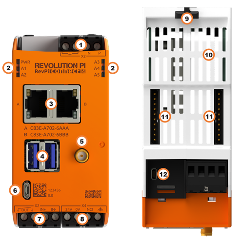
|
Note
|
The components of the RevPi may vary depending on the variant. |
| Position | Component | Application |
|---|---|---|
1 |
X2 connector RS485 |
|
2 |
6 × status LED |
|
3 |
2 × RJ45 Ethernet |
|
4 |
2 × USB A 3.2 Gen 1 |
|
5 |
RP-SMA[1] |
|
6 |
Micro-USB |
|
7 |
X2 connector |
|
8 |
X4 connector |
|
9 |
2 × locking clip |
|
10 |
Ventilation Slots |
|
11 |
2 × PiBridge |
|
12 |
Micro HDMI |
Variants #
| Item No.: | RAM | eMMC | WLAN |
|---|---|---|---|
100376 |
2 GB |
8 GB |
– |
100377 |
2 GB |
8 GB |
✔ |
100378 |
4 GB |
32 GB |
– |
100379 |
4 GB |
32 GB |
✔ |
100395 |
8 GB |
32 GB |
– |
100380 |
8 GB |
32 GB |
✔ |
For available variants see Revolution Pi Shop.
Compatibility #
The RevPi Connect 4 base module can be expanded by up to 10 expansion modules to create a Revolution Pi system:
| Left Side | Base Module | Right Side |
|---|---|---|
5 × RevPi I/O module |
RevPi Connect 4 |
5 × RevPi I/O module |
RevPi I/O Modules #
Operating System Images #
The RevPi Connect 4 is compatible with the following operating system images:
-
RevPi Bullseye
Scope of Delivery #
The scope of delivery includes
-
RevPi Connect 4 (base module)
-
X4 connector
-
2 × X2 connector
-
2 × blind plug for PiBridge
-
Product insert
Mounting and Connecting #
The RevPi was developed for use in a control cabinet. Observe the specifications for Intended Use and all Safety Instructions.
|
Warning
|
Danger to life due to electrical shock
There is a risk of fatal electrical shock when working on devices in the switch cabinet with 230 V mains voltage. ▷ Operations in the switch cabinet may only be carried out by qualified electricians. ▷ Before carrying out any operations in the switch cabinet, switch off the power supply properly. |
|
Caution
|
Damage to the device due to overheating
The ambient temperature in the switch cabinet must not exceed the maximum permissible operating temperature. ▷ Keep ventilation slots clear. ▷ Observe the installation clearances. ▷ Mount the device in the intended orientation. ▷ Do not place appliances with high input power directly next to each other. ▷ Regularly remove dust and dirt from the area around the appliance. |
Carry out mounting and connecting in the following order:
-
Mount the RevPi base module and all expansion modules on a DIN Rail.
-
Connect all expansion modules via the PiBridge plug connector.
-
Connect all other devices such as sensors and actuators. The interfaces available to you for this can be found in the section Components.
-
Connect a monitor and a keyboard if you want to operate the RevPi in the desktop mode. This is not necessary if you have a network connection to access the RevPi.
-
Finally, connect the power supply.
Access to the Device #
The RevPi is accessed in two steps:
Install all available updates as soon as the RevPi is connected to the internet. This ensures that the system is always up to date with security-relevant features.
See also:
Alternatively, access is possible without a network, see Setting up Desktop Mode.
Configuration #
The RevPi is configured in two steps:
|
Note
|
CODESYS and PiCtory cannot be used in parallel for configuration. An existing configuration via PiCtory will be overwritten by a configuration via CODESYS. The virtual devices OPC UA Server and MQTT Client can only be used via PiCtory. |
Parameterization #
The following parameters, inputs (INP) and outputs (OUT) can be configured:
RevPiStatus (INP) #
Uses bits to represent different states of the piControl driver.
| Bit | Function |
|---|---|
0 |
piControl driver is running. |
1 |
At least one connected I/O module has not been configured. |
2 |
At least one I/O module has been configured but not connected. |
3 |
An I/O module occupies more or fewer bytes in the process image than specified in the configuration. |
4 |
Without function. |
5 |
Without function. |
6 |
Digital input on X2 connector |
RevPiIOCycle (INP) #
Displays the cycle time of the PiBridge communication between the base module and expansion modules in milliseconds (ms) as an integer value.
Core_Temperature (INP) #
Displays the CPU temperature as an integer value in degrees Celsius (°C).
Core_Frequency (INP) #
Displays the CPU frequency in MHz / 10, e.g. 2400 MHz = value 240.
RS485ErrorCnt (INP) / RS485ErrorLimit (OUT) #
RS485ErrorCnt counts the errors in the communication with the RevPi I/O modules and outputs their number as an integer value.
RS485ErrorLimit1 and RS485ErrorLimit2 serve as limit values for the error handling.
|
Note
|
The communication via the serial interface RS485 to the outside is not affected, only the internal PiBridge data traffic. |
RevPiLED (OUT) #
The freely programmable LEDs can be controlled via RevPiLED, see Configuring LEDs.
| Bit | Component | Status Information |
|---|---|---|
2:0 |
LED A1 |
000 = off |
RevPiOutput (OUT) #
RevPiOutput, bit 0 controls the relay output on the lower X2 connector.
RS485 Serial Interface #
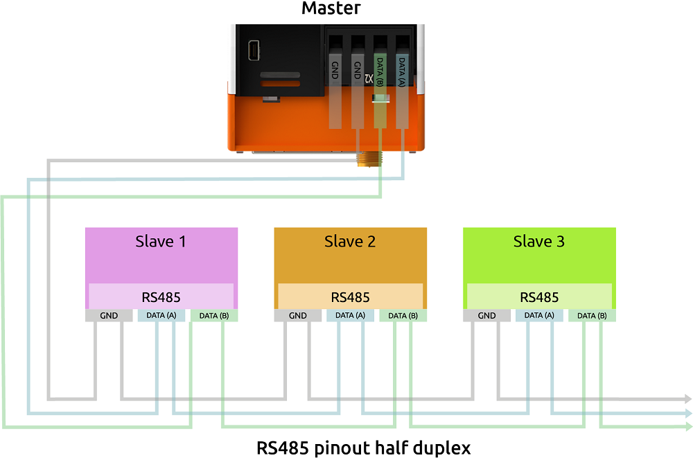
The RevPi has an RS485 interface on the upper X2 connector to connect serial devices such as sensors.
The socket has differential data line terminals P/N and reference terminals (internal GND and functional earth via 1 MOhm RC network).
Under Linux, the interface can be addressed via the device driver node with /dev/ttyRS485 .
How you use this connection optimally depends on your project environment. The network you are working with or the EMC load are individual factors that influence how you assign this connector.
We therefore cannot show you the best solution for your individual project, but we have compiled a list of the problems that can occur and tips on how you can solve them.
RS485 is a fully differential line and does not normally require a third GND line. However, due to the limits of the input receivers (maximum common mode voltage), there may be problems with the signal quality if no potential reference is used between the transmitter and receiver. However, connecting the internal GND to a line that is subject to EMC can lead to EMC problems within the RevPi Connect.
We therefore recommend that you use a common functional earth between all RS485 network participants. This gives you a good, common reference potential for the differential bus signal.
If this does not work either, you can connect the FE terminal of the RS485 connector to the third (GND) line of the bus.
You can also try to solve signal problems with the GND terminal.
Activating Termination Resistor
✓ The integrated 120 Ω terminating resistor of the RS485 interface is switched off after a restart.
▷ Log in to the RevPi via a terminal.
▷ Check out the Git repository of the command line tool rs485_config from GitLab with the command:
git clone https://gitlab.com/revolutionpi/rs485_config.git▷ Build the tool with the command:
cd rs485_config; make▷ Activate the resistor with the command:
./rs485_config <SERDEV> --set-bus-termReplace <SERDEV> with the name of the interface, e.g. /dev/ttyRS485.
▷ Check whether the resistor has been activated and display the settings of the RS485 interface with the command:
./rs485_config <SERDEV>❯❯ If the resistor is activated, Bus termination: Yes is output.
RJ45 Ethernet Interfaces #
The RevPi can be connected to a network via the RJ45 interface.
10/100 Ethernet connections are available on the RevPi, which are independent of each other. This allows the RevPi to be integrated into two different networks. The MAC addresses are printed on the front of the housing.
As of RevPi Trixie the interfaces can be addressed under Linux via:
-
Socket A:
lan0 -
Socket B:
lan1
Until RevPi Bookworm the interfaces can be addressed under Linux via:
-
Socket A:
eth0 -
Socket B:
eth1
WLAN and BT #
|
Note
|
In accordance with EU regulations, operation in the 5150 … 5350 MHz frequency band is restricted to indoor use. This restriction applies in the Member States of the European Union and in the United Kingdom (Northern Ireland). |
WLAN Interface
✓ RevPi base module with WLAN interface
✓ DHCP-enabled WLAN router
▷ Set up the WLAN connection via NetworkManager.
BT Interface
A BT interface[3] is available from standard 5.0.
▷ Activate BT via Cockpit in order to connect Bluetooth peripheral devices such as keyboards or audio devices to the RevPi.
See also:
USB Interfaces #
The RevPi has two USB A 3.2 Gen 1 interfaces. The maximum output current per USB interface is 800 mA and is only guaranteed if the RevPi is supplied with 24 V DC -15 % / 20 %.
In the event of an overload, the power is switched off at the corresponding USB interface.
Relay Output #
The RevPi provides a relay output on the lower X2 connector. This relay contact can be used, for example, to interrupt the power supply to connected hardware.
-
The relay can switch a maximum of 30 V and 300 mA.
-
The relay contact is normally open (NO) after startup.
▷ Make sure that all devices are disconnected from their power supplies.
▷ Connect the load to be switched to the OUT pins on the lower X2 connector.
▷ Connect the power supply.
The relay output is controlled in the process image via RevPiOutput, bit 0:
| RevPiOutput, Bit 0 | Function |
|---|---|
0 |
Relay contact open |
1 |
Relay contact closed |
Digital Input #
The RevPi has a digital input for a +24 V input signal on the lower X2 connector.
The input has an internal pull-down resistor.
The digital input can be used for UPS status monitoring.
▷ Make sure that all devices are disconnected from their power supplies.
▷ Connect the signal transmitter to the IN+ and IN- pins of the X2 connector.
▷ Connect the power supply.
Date and Time #
Different mechanisms are used for time management in the RevPi. They serve different purposes and complement each other.
Network Time Protocol (NTP)
Network Time Protocol (NTP) automatically synchronizes the system time of the RevPi with a time server.
Real-Time-Clock (RTC)
The RevPi is equipped with a real-time clock. When no power supply is connected to the RevPi, the RTC is powered by a backup battery. The lithium battery has a service life of approximately 10 years.
For information on replacing the battery, see Replacing the RTC battery.
See also: Real-Time Clock (RTC) in RevPi Devices.
Precision Time Protocol (PTP)
Precision Time Protocol (PTP) synchronizes devices in the network with high accuracy in microsecond range.
Trusted Platform Module (TPM) #
The RevPi is equipped with an Infineon OPTIGA™ TPM SLB 9670 Trusted Platform Module. It fulfills the requirements of TPM 2.0.
Under Linux you can address the module with /dev/tpm0.
Watchdog #
A watchdog is a timer that restarts the RevPi after 60 seconds. To prevent this from happening, the watchdog must be reset regularly as long as the system is running without errors. In the event of an error, such as a crash of the application process, there is no reset and the watchdog triggers a restart of the RevPi.
The RevPi has two independent watchdogs. There are various ways to use a watchdog under Linux. Revolution Pi and Raspbian Pi use the system manager systemd.
Integrated Watchdog
The watchdog integrated on the processor behaves like other watchdogs under Linux and can be addressed with:
-
/dev/watchdog0 -
/dev/watchdog(as standard watchdog)
External Watchdog
A second watchdog is available via the RTC module and can be addressed under Linux with:
-
/dev/watchdog1
See also:
Technical Data #
Item No.: 100376, 100377, 100378, 100379, 100395, 100380
Housing dimensions (H × W × D) |
96 × 45 × 110.5 mm |
Housing type |
DIN rail housing for TH35 mounting rail according to DIN EN 60715 |
Housing material |
Polycarbonate |
Weight |
Approx. 197 g / 224 g (incl. connectors) |
Protection class |
IP20 |
Power supply |
Typ. 10.8 … 28.8 V DC[4] |
Maximum power consumption |
20 W (incl. 2 × 800 mA USB load)[5] |
Approved operating temperature |
-25 … +55 °C |
Approved storage temperature |
-40 … +85 °C |
Max. relative humidity (at 40 °C) |
93 % (non-condensing) |
Interfaces |
|
Connectors |
|
Compute Module |
Raspberry Pi Compute Module 4 |
Processor |
Broadcom BCM2711, quad-core Arm Cortex-A72 |
Clock rate |
1.5 GHz |
Processor cooling |
Passive with heat sink |
RAM |
2 GB LPDDR4 (Item No.: 100376, 100377), 4 GB LPDDR4 (Item No.: 100378, 100379), 8 GB LPDDR4 (Item No.: 100395, 100380) |
Flash memory |
8 GB (Item No.: 100376, 100377), 32 GB (Item No.: 100378, 100379, 100395, 100380) |
Trusted Platform Module |
TPM 2.0 Infineon OPTIGA™ TPM SLB 9670 |
WLAN / BT |
|
Number of digital inputs |
1 |
Digital input type |
24 V DC control voltage (e.g. for power-good signal of a UPS) |
Input threshold |
Approx. 10 V DC (0 → 1) or 7 V DC (1 → 0); input current 2.4 mA (according to IEC 61131-2) |
Number of digital outputs |
1 |
Output type |
Opto-decoupled solid state relay (NO), max. 30 V, 300 mA DC, any polarity |
Software interface of input and output |
Via GPIOs and process image |
Hardware watchdog |
Watchdog in RTC device, freely configurable watchdog character device |
Compatible RevPi modules |
|
EMC interference emission |
According to IEC 61000-6-4 (emission standard for industrial environments) |
EMC immunity |
According to IEC 61000-6-2 (immunity standard for industrial environments) |
RTC buffer |
CR2032 lithium battery, lifetime approx. 10 years |
Optical display |
6 status LEDs; |
Conformity |
CE, UKCA |
UL certification |
UL File No. E494534 |