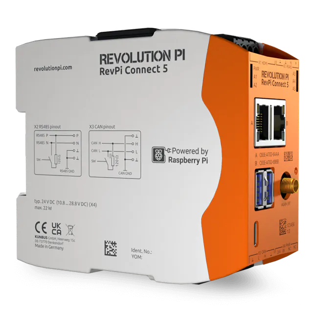
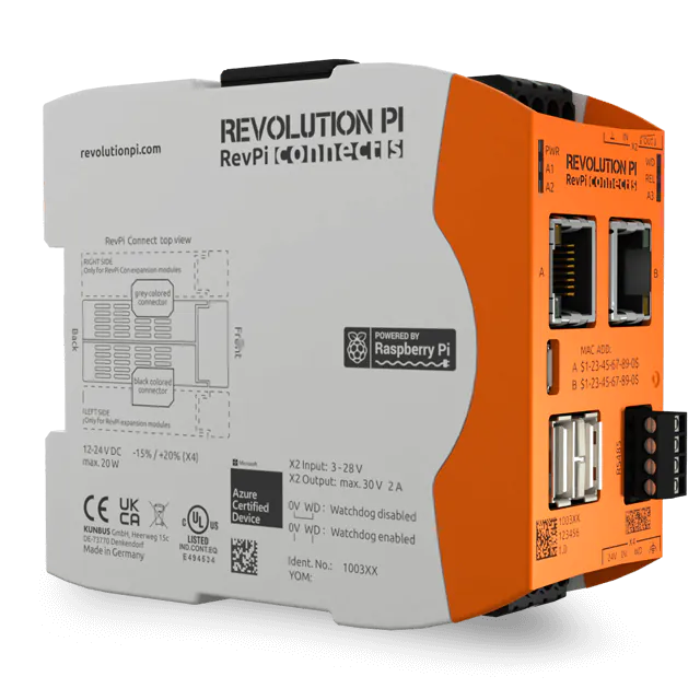
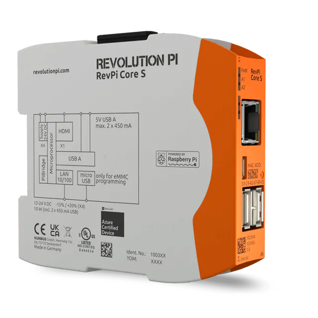
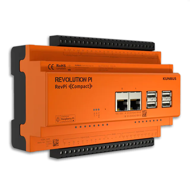
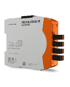
You can use PiCtory to configure your Revolution Pi system. In this chapter we will describe the setting values of the Value Editor for the four relay outputs OUT1 to OUT4 of the RevPi RO.
Requirements:
- You have installed a web browser on your PC (e.g. Chrome or Firefox).
- Your RevPi base module and RevPi RO are connected via the PiBridge.
- The RevPi base module is connected to your network.
Let’s go!
- Open your web browser.
- Enter the IP address of your RevPi base module in the address bar of your web browser.
The login window opens.
- Log in with the username admin.
- Enter your password. You can find it on the sticker on the side of your RevPi base module.
- Click on LOGIN.
You will now see the current device status of your RevPi base module.
- Click on the tab APPS.
- Click on the button START next to the entry PiCtory to open PiCtory.
PiCtory opens.
- Select your RevPi base module from the Device Catalog.
- Drag and drop your RevPi base module on to the Configuration Board.
- Open the folder I/O Devices in the Device Catalog.
- Select the RevPi RO.
- Drag and drop the RevPi RO into the empty slot on the Configuration Board, to the left side of the RevPi base module.
- Define the basic settings for your modules in the Device Data area. This entry is optional. If you use a lot of devices and wish to process the data in another program later, then this entry can be very helpful.
- Configure the outputs in the Value Editor. You will find the detailed setting values at the end of this chapter.
- Click on File > Save. This saves your configuration.
- Click on Tools > Reset Driver. This activates the changes.
Setting the Warning Limit for Switching Operations
You can use the four memory variables in the Value Editor to set a threshold value for the number of switching operations for each relay output. If this threshold value is exceeded, the RevPi RO switches on the red status LED for the respective output and generates a warning at the status bit for the respective relay.
The default value is 0. A threshold value of 0 generates no warning at the status bit and the status LED is not triggered.
You can query the current number of switching operations with piTest -C RO-ADDRESS
.
You can find an overview of recommended threshold values in the following table. The values are based on the data sheet of the relay module used:
Type of load |
Voltage |
Current |
Recommended threshold value for warning limit |
---|---|---|---|
Resistive load | 250 V AC | 3 A | 100 000 |
30 V AC | 100 000 | ||
250 V AC | 5 A | 80 000 | |
30 V AC | 80 000 | ||
Inductive load | 250 V AC | 2 A | 100 000 |
30 V AC | 100 000 | ||
No load | 0 V | 0 A | 1 000 000 |
Status Byte in the Process Image
Name |
Data Type |
Quantity |
Offset |
Description |
---|---|---|---|---|
Status | BYTE | 1 | 0 | Bit-coded status of the outputs. Bits 0 to 3 show the current warning status of relays 1 to 4. 1: Warning at the relay (threshold exceeded). 0: no warning. |