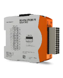
Overview
PIN | |||
1 | Output 1 | V+ | positive output for voltage ranges channel 1 |
2 | Output 2 | V+ | positive output for voltage ranges channel 2 |
3 | Output 1 | I+ | positive output for current ranges channel 1 |
4 | Output 2 | I+ | positive output for current ranges channel 2 |
5 | Output 1 | – | shared ground of output channels 1 und 2 (voltage and current) |
6 | Output 2 | – | shared ground of output channels 1 und 2 (voltage and current) |
7 | Output 1 | – | shared ground of output channels 1 und 2 (voltage and current) |
8 | Output 2 | – | shared ground of output channels 1 und 2 (voltage and current) |
9 | RTD 2 | white | negative measuring current for 3- & 4-wire; for 2-wire jumper to pin 18 |
10 | RTD 1 | white | negative measuring current for 3- & 4-wire; for 2-wire jumper to pin 12 |
11 | Input 4 | – | negative input for current or voltage measurement channel 4 |
12 | RTD 1 | white | negative measuring input, 2-, 3- and 4-wire, Channel 1 |
13 | Input 4 | * | a jumper must be installed from here to pin 15 for current measurements |
14 | RTD 1 | red | positive input, 2-, 3- and 4-wire, Channel 1 |
15 | Input 4 | + | positive input for current or voltage measurement channel 4 |
16 | RTD 1 | red | positive measuring current, only for 4-wire, channel 1 |
17 | Input 3 | – | negative input for current or voltage measurement channel 3 |
18 | RTD 2 | white | negative measuring input, 2-, 3- and 4-wire, channel 2 |
19 | Input 3 | * | a jumper must be installed from here to pin 21 for current measurements |
20 | RTD 2 | red | positive input, 2-, 3- and 4-wire, channel 2 |
21 | Input 3 | + | positive input for current or voltage measurement channel 3 |
22 | RTD 2 | red | positive measuring current, only for 4-wire, channel 2 |
23 | Input 2 | – | negative input for current or voltage measurement channel 2 |
24 | Input 1 | – | negative input for current or voltage measurement channel 1 |
25 | Input 2 | * | a jumper must be installed from here to pin 27 for current measurements |
26 | Input 1 | * | a jumper must be installed from here to pin 28 for current measurements |
27 | Input 2 | + | positive input for current or voltage measurement channel 2 |
28 | Input 1 | + | positive input for current or voltage measurement channel 1 |
Overview of interfaces
Outputs
PLEASE NOTE
Current and voltage outputs can only be selected alternatively for one output channel (either only the V or only the I output of one channel is active, depending on the configuration in PiCtory)!
Output 1 | |
PIN | |
1 | V+ positive output for voltage ranges channel 1 |
3 | I+ positive output for current ranges channel 1 |
5 | – shared ground of output channels 1 und 2 (voltage and current) |
7 | – shared ground of output channels 1 und 2 (voltage and current) |
Output 2 | |
PIN | |
2 | V+ positive output for voltage ranges channel 2 |
4 | I+ positive output for current ranges channel 2 |
6 | – shared ground of output channels 1 und 2 (voltage and current) |
8 | – shared ground of output channels 1 und 2 (voltage and current) |
Inputs
Input 1 | |
PIN | |
24 | – negative input for current or voltage measurement channel 1 |
26 | * a jumper must be installed from here to + for current measurements |
28 | + positive input for current or voltage measurement channel 1 |
Input 2 | |
PIN | |
23 | – negative input for current or voltage measurement channel 2 |
25 | * a jumper must be installed from here to + for current measurements |
27 | + positive input for current or voltage measurement channel 2 |
Input 3 | |
PIN | |
17 | – negative input for current or voltage measurement channel 3 |
19 | * a jumper must be installed from here to + for current measurements |
21 | + positive input for current or voltage measurement channel 3 |
Input 4 | |
PIN | |
11 | – negative input for current or voltage measurement channel 4 |
13 | * a jumper must be installed from here to + for current measurements |
15 | + positive input for current or voltage measurement channel 4 |
RTD channels
RTD1 | |
PIN | |
10 | RTD connection white (negative measuring current for 3- & 4-wire; for 2-wire jumper to pin 12) |
12 | RTD connection white (negative measuring input, 2-, 3- and 4-wire) channel 1 |
14 | RTD connection red (positive measuring current, 2-, 3- and 4-wire) channel 1 |
16 | RTD connection red (positive measuring current, only 4-wire) channel 1 |
RTD2 | |
PIN | |
9 | RTD connection white (negative measuring current for 3- & 4-wire; for 2-wire jumper to pin 18) |
18 | RTD connection white (negative measuring input, 2-, 3- and 4-wire) channel 2 |
20 | RTD connection red (positive measuring current, 2-, 3- and 4-wire) channel 2 |
22 | RTD connection red (positive measuring current, only 4-wire) channel 2 |