How to Configure Digital I/O Modules.

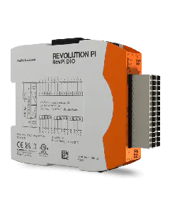
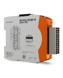
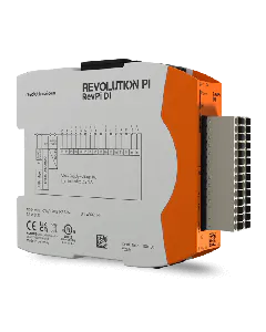
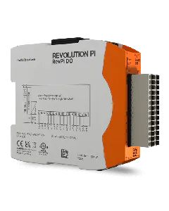
PiCtory helps you to configure your RevPi DIO/DI/DO. In this chapter we describe the setpoints of the Value Editor in more detail.

Inputs

In the input area you can make settings for all parameters your RevPi module receives, for example, values of a temperature sensor. In the memory area you can select how the inputs are to be evaluated. Optionally, you can also configure the inputs as encoders and activate a counter function.

Detailed information about the Memory section and the Encoder and Counter functions can be found in the corresponding sections of this chapter.

Name Data type Quantity Offset RevPi DIO RevPi DI RevPi DO Description
Input WORD 1 0 X X Current values at the inputs.
Bits 0 – 15 (DI) or 0-13 (DIO) show the current values of inputs 1 – 16 (DI) or 1-14 (DIO).
Output Status WORD 1 2 X X Bit-coded status of the outputs.
Bits 0 – 15 (DO) or 0-13 (DIO) indicate the current error state of outputs 1 – 16 (DO) or 1-14 (DIO).1: Output error (Switch-off due to overtemperature, overload..).0: No error
Status WORD 1 4 X X X module status

Note!: Values of bit 0-7 are only valid for RevPi DIO and DI. These bits are not assigned for RevPi DO, since this module has no inputs ICs.

Bit 0: No communication to the input IC

Bit 1: UV1* on input 1 – 8

Bit 2: UV2* on input 1 – 8

Bit 3: Overtemperature** on input 1 – 8

Bit 4: UV1* on input 9 – 16

Bit 5: UV2* on input 9 – 16

Bit 6: Overtemperature** on input 9 – 16

Bit 7: Error prompt of the input IC

Note!: Values of bit 8-16 are only valid for RevPi DIO and DO. For RevPi DI, these bits are not occupied because the module has no output ICs.

Bit 8: No communication to the output IC

Bit 9: CRC error on output IC

Bit 10: Error prompt of the output IC

Bit 11 – 15: undefined

Counter DINT 16 6 X X Current values of the counter or encoder function.

* UV1: The supply voltage for the input ICs has dropped below 7 volts. The alarm is cancelled when the supply voltage rises above 9 volts again.

* UV2: The supply voltage for the input ICs has dropped below 14 volts. The alarm is cancelled when the supply voltage rises above 16.5 volts again.

Channels 1-8 and 9-16 have separate bits for UV1 and UV 2 because there are two individual ICs in the module that generate this signal. However, the voltage is always identical on both ICs. Therefore, both ICs set their error bit in UV1 or UV2.

** The input ICs signal an overtemperature alarm when 135 °C is exceeded.

Outputs

In the output section you can configure settings for all process values sent by your RevPi module. In the memory area you can select how the outputs are set. Optionally you can switch on a PWM function.

Detailed information on the Memory and PWM functions can be found in the corresponding sections of this chapter.


Name Data type Quantity Offset RevPi DIO RevPi DI RevPi DO Description
Output WORD 1 70 X X Current values at the outputs.

Bits 0 – 15 (DO) or 0-13 (DIO) indicate the current values of outputs 1 – 16 (DO) or 1-14 (DIO).

PWM

(1 – 16)

USINT 16 72 X X Current PWM values in % for outputs 1 – 16 (DO) or 1-14 (DIO).
These values are only valid if the PWM function is enabed for the respective output.

Memory

In the Memory area you can define how the individual inputs are to be evaluated and how the outputs are to be set.

Name Data type Quantity Offset RevPi DIO RevPi DI RevPi DO Description
InputMode BYTE 16 88 X X Select the mode for each input.

Direct -> Current value of the input can be retrieved.

Counter, rising edge -> Rising edges are counted at the input.

Counter, falling edge -> Falling edges are counted at the input.

Encoder -> This input is used for encoder function. ATTENTION: 2 inputs required for encoder function (see section „Encoder“.)

InputDebounce WORD 1 104 X X This is where a time for the debounce filter is specified for all inputs. This time indicates when a changing state at the input is considered stable. Possible values are Off, 25 µs, 750 µs and 3 ms.
OutputPushPull WORD 1 106 X X Specifies whether the outputs are operated in push-pull or highside mode.
OutputOpenLoadDetect WORD 1 108 X X Specifies whether open-load detection is enabled for the outputs.
OutputPWMActive WORD 1 110 X X Specifies whether PWM is enabled for the outputs.
OutputPWMFrequency BYTE 1 112 X X This is where, for all outputs that are to be operated in PWM mode, the frequency at which the PWM signal is to be generated is specified. In general, the higher the frequency, the higher the step size in which the clock ratio can be set.

Counter

You can optionally switch on a counter function for each of the 14 inputs. As the name already says, you can, for example, count the number of times a turnstile or a key has been pressed.

You can find an example of this in our video tutorials. For each counter, a 32 bit value is then available in the process image. The current counter value is returned as signed 32 bit value.

Encoder

You can configure all inputs as encoders. In combination with the PWM function, this can be helpful if you want to control parts of quantities. For example, you can use it to regulate a water supply or to dim lights.

You can use a maximum of 5 encoders.

For each encoder you need 2 inputs. You must always use the inputs in pairs.

Example:
Input 1 and 2,

Input 3 and 4

Input 13 and 14 ( Input 15 and 16 at RevPi DI)

It is important that you always connect the first encoder channel to an odd input. If you don’t do that your encoder will not be recognized.

The current encoder value is returned as signed 32 bit value for the first channe.

PWM

You can switch on an optional PWM function for each of the 14 outputs.

The PWM function is helpful if you want to, for example, control parts of quantities. You can use it to regulate a water supply or dim lights.

If PWM is switched on, a whole byte value from 0 to 100 is transmitted instead of one bit per channel, which defines the pulse width at the output as a percentage. By configuration, one of the following PWM frequencies can be set for each module:


PWM frequency Resolution of the smallest increment in percent (step size)
40 Hz 1%
80 Hz 2%
160 Hz 4%
200 Hz 5%
400 Hz 10%

The current step size in % is set via an unsigned 8 bit value.