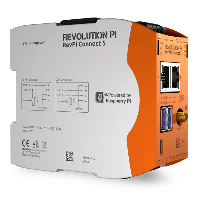
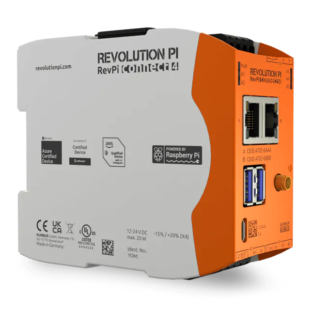
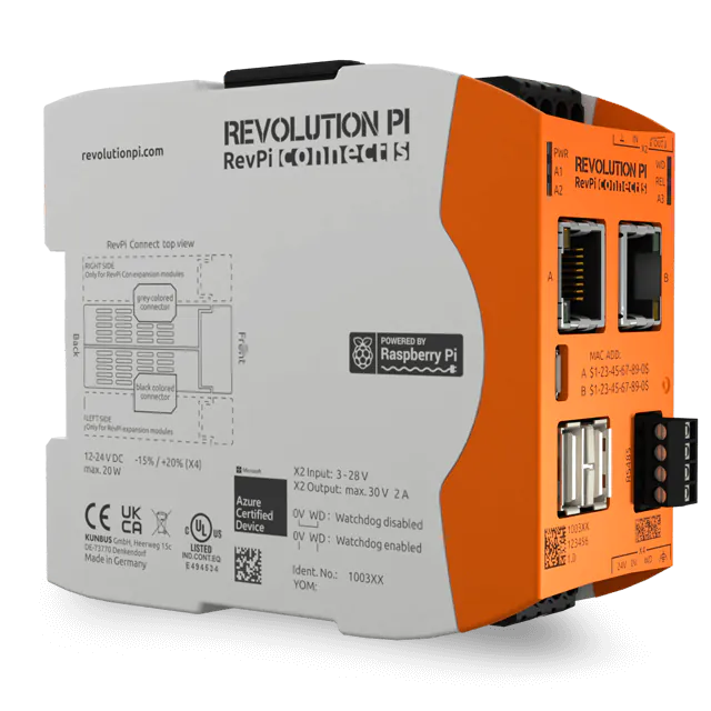
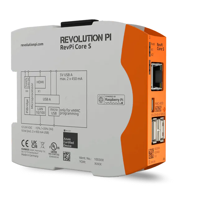
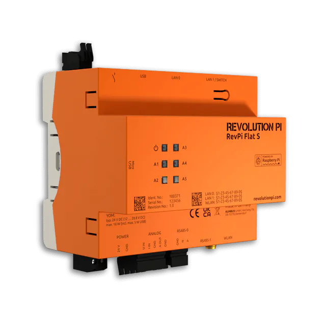
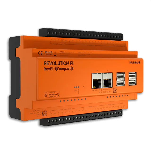
If you want to use the configuration values of your RevPi Flat also in other applications, you need a configuration file which contains the basic settings of your RevPi Flat .
If you’d like to link up several RevPi modules then you need a configuration file alongside the physical link. This configuration file will inform your RevPi Flat about the position and the basic settings of the modules.
Such file can be created by PiCtory.
In this tutorial we explain the user interface of PiCtory and create a configuration file.
Requirements:
- You have installed a web browser on your PC (e.g. Chrome or Firefox).
- RevPi Flat is connected to your network.
- You know the IP address of your RevPi Flat .
Let’s go!
- Open your web browser.
- Enter the IP address of your RevPi Flat in the address bar of your browser.
The logon window opens.
- Log on with the username “admin”.
- Enter your password. You can find it on the sticker on the side of your RevPi Flat.
- Click on “Login”.
You can now see the current device status of your RevPi Flat.
- Click on the “Apps” tab.
- Click on the start button behind the entry “PiCtory” to open PiCtory.
Done, PiCtory opens!
Let’s take a look around first!
In the following section we explain what you can do in the individual work areas which are listed here. After that, we”ll continue working on our configuration file.
Configuration Board
The configuration board is your workspace. You can configure all devices that you have activated here.
There are a few rules to follow when composing your devices:
- The RevPi Flat forms the basis for your project.
- Additionally you can use virtual devices.
Device Catalogue
In the device catalog you can find all adapters from the RevPi product family. If you have to write your own drivers for a particular hardware, you can add them to the device catalog as adapters. You have to create a RAP file (RevPi adapter profile file) for this purpose.
Please note that the RevPi Flat does not have a PiBridge connector. Therefore, you can only use the virtual adapters from the device catalog together with the RevPi Flat .
Device Data
In this window you can make the basic settings for your adapters (e.g. device names).
Value Editor
In the value editor you can define the input and output ports you want to use. You can also assign names to the individual connections.
Set Up the Workplace
The adapters on the configuration board are too big? The device data window disturbs you and the configuration board is too small? No problem, everything can be adjusted!
Changing the Size of the Adapters on the Configuration Board
- Click on the “Display Size” selection window.
- Set the size for displaying the adapters.
Show and Hide Windows
- Click on the black button to hide a window.
- You can restore the window by clicking the same button again.
Change Window Size
- Place the cursor on the frame of the window you want to enlarge.
The arrow appears as shown below.
- Keep the left mouse button pressed and adjust the window size according to your requirements.
Let’s go on!
- Select the RevPi Flat from the device catalog.
- Drag and drop it onto the configuration board.
- Optionally, select a virtual device from the device catalog.
- Drag and drop it into the empty column on the configuration board.
- Click on the RevPi Flat.
- There are two work areas below the configuration board. Your adapters can be configured here.
- Define the basic settings for your adapters in the “Device Data” area.
The following values should help you to identify your adapter easily:
- Name of the adapter (Device Name)
- Device tag (BMK)
- Comment (Comment)
If you do not enter any values, the values are used which are stored in the RAP file.
- Defining your Inputs and Outputs The values you select here do not determine the number of physical inputs and outputs. These values determine whether the inputs and outputs are addressed via a Boolean variable or via a 16-bit variable. Choose the higher value for the boolean variable and the lower value for the 16-bit variable.
-
- Set the values for your adapter device in the value editor.
Example: How to Connect a Sensor
Let’s assume you want to connect a sensor to the first analog input of the RevPi Flat and the file shall later be used in logi.CAD3.
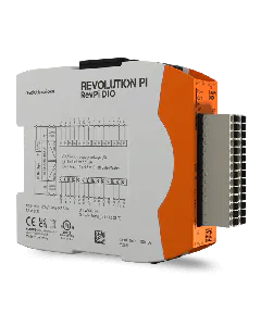
We select the RevPi DIO as we want to connect a sensor to the first input of the RevPi DIO. The file is to be used later in logi.CAD3.
- Assign the name “Sensor1” to the input I_1 (or Input_Pin_1), so that you can identify this setting in logi.CAD3.
- Check “Export” in order to use the variable for this input in logi.CAD3.
- Click on “File>Save As” to save the file.
- Specify the project name.
- Click on “OK”.
- Click on “Tools>Reset Driver” to activate the changes for the adapter.
-
- If you are sure, click on “OK”.
- Click on “File>Export”.
A window opens.
Here you can specify the format of the file and the file name.
You can choose from the following formats:
- Export 01 creates a file that is suitable for using it in logi.CAD3.
- Export 02 generates an offset list, that you can use as basic information for your own C program.
- Export 03 creates a symbol list, that is suitable for using it in the Soft-PLC IBHsoftec.
- Export 04 creates an offset list, which you can use in Codesys.
- Export 05 creates an export for LogicLab.
- Select a format you want to continue working with.
- Select “Download” to save the export file as json file or
- Select “Show Only” to view the export file.
- Enter a file name in the field “Export Filename”.
- Click on “OK”.