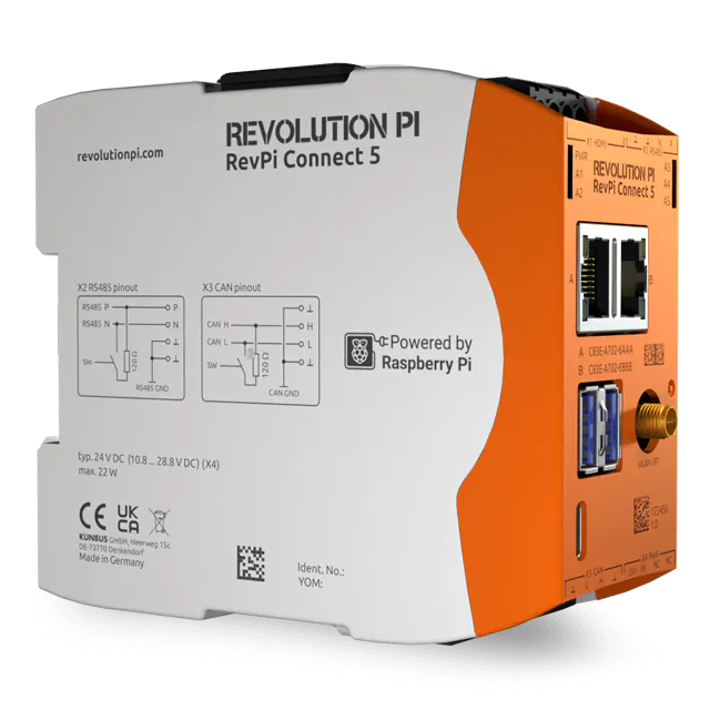
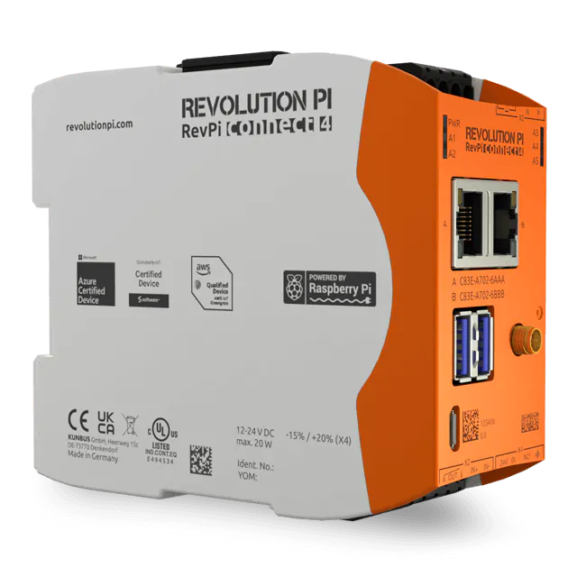
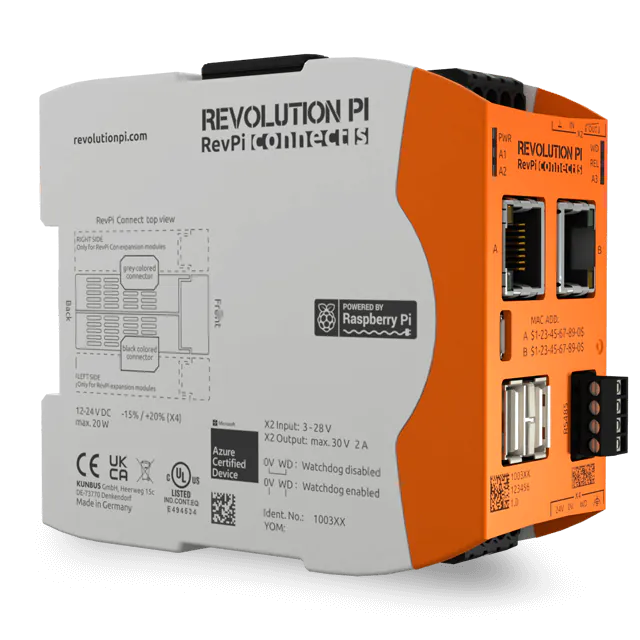
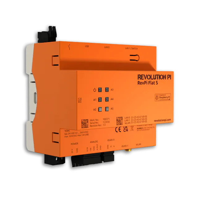
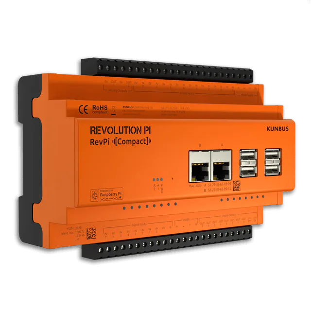
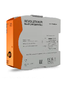
In the following example, use our RevPi Connect as a Modbus RTU master and connect an RFID card reader to it.
You need:
- RevPi Connect
- Slave
- Matching cables with D-Sub 9 connectors
- Adapter (e.g. shop article 200018 oder 200019)
- Internet connection
Requirements:
- A web browser, e.g. Google Chrome or Mozilla Firefox.
- RevPi Connect is located in your network.
Connecting the Slave to the RevPi Connect
- Connect a USB port of the RevPi Connect to the adapter.
- Connect the adapter to the slave via the D-Sub 9 socket.
- Connect your RevPi Connect to the power supply.
Determine Modbus RTU network data
In order to configure the slave, we need some data beforehand, so that we can address the slave via our RevPi Connect. We find this data in the user manual of our slave.
In this example we use the RFID card reader “Iveno RFID MODBUS Reader RFID-MB-10” as slave.
- Note the following data from the user manual of your slave:
Data type |
Value (Example data for the RFID card reader) |
Interface | /dev/ttyUSB0 |
Baud rate | 9600 |
Data bits | 8 |
Stop bits | 1 |
Parity | None |
Slave adress | 1 |
Modbus function | Read Holding Registers |
Modbus register transponder code [0] | 1000 |
Modbus register transponder code [1] | 1001 |
Modbus register transponder code [2] | 1002 |
Modbus register transponder code [3] | 1003 |
Modbus register transponder code [4] | 1004 |
Enable ModbusRTU Master function
- Start RevPi Status.
- Click tab SERVICES.
- Enable Modbus Master.
- Click button Save All.
You can also activate the Master function on the command line.
Enter the following command: sudo revpi-config enable pimodbus-master
.
ModbusRTU Master configuration
- Start PiCtory.
- In the Device Catalog, open the folder Virtual Devices.
- Select ModbusRTU Master.
- Hold down the left mouse button and drag the Modbus-RTU Master to your RevPi Connect.
Set the basic settings for your adapters in the “Device Data” window. This entry is optional. If you use a lot of devices and want to process the data later in another program, this input can be very helpful.
You define the settings for the serial connection in the “Value Editor”. We have already determined the values for our slave from the user manual of the sensor:
- device_path: USB device path (see lsusb –v und ls /dev/ttyU*)
- baud_rate: 9600
- parity: None
- data_bits: 8
- stop_bits: 1
- Right-click the Modbus RTU Master on the Configuration Board.
- A context menu opens.
- Select the entry “Extended Data” to open an input mask.
This is where we set the Modbus commands. In this example, we need a command to read the values of the RFID sensor. We have already gathered the necessary information from the sensor’s operating instructions:
Slave Addr: 1
Function Code: READ_INPUT_REGISTERS
Register Addr.: 1000
Quantity of Registers: 5
Save configuration
Click on „File>Save“ to save the file.
Click on “Tools>Reset Driver”. This activates the changes for the adapter.
Query values in the process image
- Open command line and enter following command:
piTest -v Input_Word_1
- You get the information of the location of your values in the process image:
variable name: Input_Word_1 offset: 11 length: 16 bit
The values are in the process image from address 16 onwards. We need to read 10 bytes.
We enter the following command and see our values:”piTest -r 11,10, h”. If we now hold the RFID card to the card reader, we can observe the change of the values in the process image.
piTest -r 11,10,h 00 00 00 00 00 00 00 00 00 00 00 00 00 00 00 00 00 00 00 00 00 00 00 00 00 00 00 00 00 00 04 00 00 00 1b 00 87 00 2b 00 04 00 00 00 1b 00 87 00 2b 00 04 00 00 00 1b 00 87 00 2b 00 [...]