How to Configure RevPi DIO by Using PiCtory

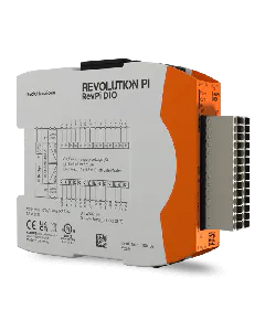
Using the RevPi DIO module, one can use the inputs not only to directly read digital input values but also as counters of falling or rising edges or respectively 2 inputs together at the end of an incremental encoder.

Outputs can not only output a digital signal but also a pulse-width modulated (PWM) signal.

The same obviously goes for the RevPi DI and RevPi DO module – the following explanation however only mentions DIO.

PiCtory Screenshot
PiCtory GUI

If one inserts a RevPi DIO module into PiCtory and clicks it, one can select the number of inputs and outputs in Device Data section below left in the Input and Output column. In doing so it does not change the number of physical I/Os but the number of variables by which you can be addressed. The standard setting is that every I/O-Pin can be addressed via an own BOOL Variable Input_Pin_n or Output_pin_n respectively. By choosing the lower number, all the I/Os are coded in a 16-bit variable as a bit field.

The numbers in the check box are bigger as the optional variables for counter, encoder and PWM also have to be counted. One also has to take care that the process image from all three modules is structured in the same way but certain bytes are not used. As for DO for example the bytes for the inputs, DIO the bits for pin 15 and 16 that are not connected here.

In Value Editor to the bottom right, one can give the variables other names. The names are later adopted in, for example, logi.CAD3. There is however also a ioctl call in the picontrol driver to get a position in the process image for a name. It means one can alter the hardware configuration and therefore the structure of the process image without having to alter the application accessing it. For it to function, every variable obviously has to have a different and clear name.

Secondly one can give variables a start value. It is particularly important for the values of the MEM version as it the means by which the behaviour of the module is configurated.

Value Editor Screenshot

One of four operating modes can be selected for the 16 InputMode_n variables:

  • Direct: the current start value stands in the Input_Pin_n variable
  • Coutner, rising edge: rising edges are counted
  • Coutner, falling edge: falling edges are counted
  • Encoder: encoder pulses are counted at this and the following input.
PLEASE NOTE
No more than 6 inputs can be configurated simultaneously as counters or encoders on one module.

The counter and encoder value stands as a 32-bit value in the counter_n variable.

Using InputDebounce, contact bounce suppression can be regulated across all inputs. The following values are possible: off, 25µs, 750µs, 3ms

OutputPushPull defines whether the outputs work in push-pull or high-side switch mode. The variable is a bit field – this means if bit 0 has the value of 1, output 1 works in push-pull mode, bit 1 is valid for output 2 etc. The standard value is 0, therefore all outputs in high-side switch mode.

OutputOpenLoadDetection defines whether the connection to the load is open or closed. The variable is a bit field – this means if bit 0 has the value of 1, the OutputOpenLoadDetection is active for the first channel. For the configuration and analysis of this function, the monitoring for the corresponding output channels must first be activated in PiCtory via “OpenLoadDetect”.

In case of an error, the corresponding bits are set in the variable “Output Status” (Offset 2). Please refer to the tutorial page How to Configure Digital I/O Modules. As a result, all outputs are switched off and the status LED on the DIO/DO module flashes permanently red, as in all error cases.

Note: OpenLoadDetection is only active when the monitored output is Low. If voltage is applied, monitoring is deactivated. Furthermore, it is not possible to clearly separate overtemperature, overload and openLoad.

OutputPWMActive is also a bit field. If a bit is 0, the value of Output_Pin_n is issued directly. If the bit is 1, a PWM signal is issued instead. The value that should be issued has to be written in the PWM_n variable. %-values from 0 to 100 can be written in PWM_n variables. 0% always means off, 100% always means on. At 20%, the output is for example on for a one-fifth period and off for four-fifths of a period. The period lengths and the frequency respectively can be set via the OutputPWMFrequency at between 40Hz and 400Hz. At 40Hz, all values between 0% and 100% can be issued in steps of one. At 400Hz only 10% steps are possible – therefore 0%, 10%, 20% and so on to 100%.

There are still 2 status values:

Output_Status is a bit field with 16 bits for the 16 outputs.

.