How to Create a Configuration File with PiCtory.

If you want to connect several RevPi modules to each other, you will need a configuration file in addition to the PiBridge, which physically connects the modules. This configuration file tells your RevPi Connect which expansion modules are in which position and which basic settings these modules have.
You can create the configuration file with PiCtory.
In this chapter we will explain the user interface of PiCtory and create a configuration file..

Requirements:

  • A web browser, e.g. Google Chrome or Mozilla Firefox
  • RevPi Core is located in your network.

Let’s go!

  • Open your web browser.
  • Enter the IP address of your RevPi Cores in the address bar of your browser.

The login window appears.

pictory-anmelden


    • Log in with the username “admin”.
    • Enter your password. It can be found on the sticker on the side of your RevPi Core.
    • Click on „Login“

    The status page opens.

    • Click “Apps” tab
    • Click the start button behind the entry “PiCtory” to start PiCtory.

    PiCtory opens.

    Let’s take a look around first!
    So that you know what you can do in the individual work areas that you see in front of you, we will explain this to you in the following section. Afterwards we will continue working on our configuration file.

    Configuration Board
    On the configuration board you can assemble the adapters in the same way as they are arranged on the DIN rail. PiCtory supports you in your project by giving you feedback if it is not possible to assemble your devices.There are a few rules for putting together the devices, which you have to observe:

    1. RevPi Core forms the basis of every project
    2. Gateways may only be integrated into the project on the far right or far left.

    To add a new device to this virtual DIN rail, you must first create a new slot. To do this, right-click on the RevPi Core and select “Insert column (right/left)” in the context menu. Then you can insert an adapter from the device catalog (see next section). An adapter can be a hardware module that is connected to RevPi Core via the PiBridge or a driver software for which memory space is reserved in the process image.

Device Catalog
In the device catalog you will find all available adapters. If you have to write your own drivers for a special hardware, you can also add them to the device catalog as adapters. To do this, you need to create a RAP file (RevPi Adapter Profile File).

Data sheet
The data sheet shows you detailed information about a device that you have clicked on in the device catalog or on the configuration board.

Value Editor
In the Value Editor, you can specify which input and output ports you want to use. You can also name the individual connections.

Set up
The adapter icons on the Configuration Board are too large? The data sheet window disturbs you while working and the size of the configuration board is too small? No problem, everything can be adjusted!Changing icon size of the adapterss on the Configuration Board

  • Click on the selection window “Display Size”.
  • Set the desired icon size in which the adapters are to be displayed.

Show and hide windows

  • Click on the black button to hide a window.
  • You can restore the window by clicking the same button again.

Change window size

  • Place the cursor on the frame of the window you want to resize.

The arrow shown below appears.

  • Hold down the right mouse button and adjust the window to your desired size.

Let’s move on!:

  • Right-click on the RevPi Connect located on the Configuration Board.
  • In the context menu, select “Insert right column”.


An empty column is created to the right of the RevPi Core.

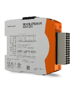
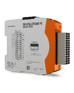
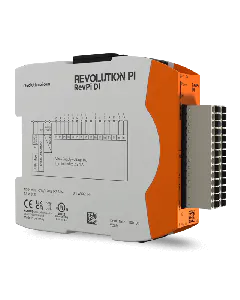
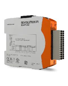
  • Select RevPi DIO from the device catalog.
  • Drag and drop it into the empty column on the Configuration Board.

  • Click on the RevPi Connect
  • Below the Configuration Board, 2 workspaces will now open. Here you can configure your adapters.
  • Set the basic settings for your adapters in the area “Device Data”.

The following values should help you to recognize your adapter easily.

  • Adapter name
  • Device tag (BMK)
  • Comments

If you do not enter values, the values stored in the RAP file are used.

    • Define your inputs and outputs. The values you select here do not determine the number of physical inputs and outputs. These values determine whether the inputs and outputs are addressed via a Boolean variable or a 16-bit variable. Choose the higher value for the Boolean variable and the lower value for the 16-bit variable.


  • Set the values for your adapter device in the value editor.
  • For example, if you click the RevPi DIO, you will see the following in the value editor:

Example:
We select the RevPi DIO, because we want to connect a sensor to the first input of the RevPi DIO. Later, the file will also be used in logi.CAD3.

    • So that we can recognize this setting in logi.CAD3, we give the input Input_Pin_1 the name “Sensor1”.
    • In order to use this variable in logi.CAD3, we set a check mark at “Export”.


  • Click on „File>Save“ to save the file.


  • Click on “Save as”.
  • Enter a file name.

  • Click on “Tools>Reset Driver”. This activates the changes for the adapter.


  • Click on „OK“.

  • Click on „File>Export“.


You can choose from 2 file formats:

      • Export 01 creates a file that is suitable for use in logiCAD3.
        Export 02 creates an offset list, which you can use as basic information for your own C-program.
  • Select the file format you want to continue working with.

  • Enter a filename.
  • Click on „Ok“.

Congratulations! You have just created your first configuration file!