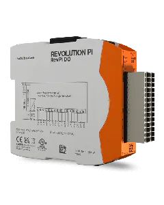
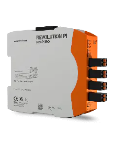
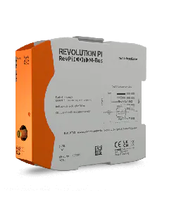
You can use the digital output to switch external devices on and off, for example. It is designed as a potential-free relay contact. Control is therefore effected via a mechanical connection of the pins.
The relay contact may have a maximum load of 30 VDC or 24 VAC and 2 A!
Attention: a higher voltage can lead to the destruction of the device.
Great feature: A suppressor diode is connected in parallel to the relay contact to reduce the switching sparks that occur when switching inductive loads. This reduces wear. An external freewheeling diode or similar is not required.
Control with piTest
Using piTest program, you can set the digital output (or relay) with the option “-w”:
Activate the relay with piTest -w DOut,1
Deactivate the relay with piTest -W DOut,0
Direct Control
You can use the “gpio” program for direct control of the relay via operating system functions. First you must switch the corresponding GPIO pin – in this case pin 28 – as the output. Then you can set the output with 1 for switch on and 0 for switch off. The example below shows the corresponding sequence of commands:
- Set the pin as the output with
gpio mode 28 out
- Switch the output on with
gpio write 28 1
- Switch the output off with
gpio write 28 0