Controlling Inputs/Outputs not using piControl

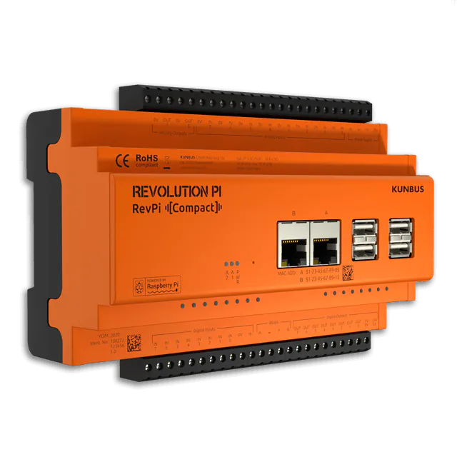
Normally, you access the inputs and outputs of your RevPi Compact via the process image managed by piControl, similar to a standard industrial control system. But there is another option and it is up to you which way you choose.

The point is that the inputs and outputs are integrated in the industrial I/O (iio) and general purpose I/O (gpio) subsystems in the Linux kernel and therefore can be manipulated directly. You can do this by your favorite programming language as well as directly on the command line.

However, in doing so you waive the benefits offered by the process image:

  • As an abstraction layer, the process image ensures that different systems work together smoothly, such as control software, HMI interfaces, cloud connections or fieldbus daemons.
  • The process image allows to use your software also on other devices of the Revolution Pi family.

But direct control as well has certain advantages:

  • Direct control can be useful for quick testing and prototyping.
  • You can use it to implement particular requirements which are not covered by piControl.
  • You can use existing software on the RevPi Compact which already uses the iio and gpio interfaces of the kernel.

If you choose piControl or direct control should be considered carefully. Anyway, whatever project you want to implement, with these two options you have always the right tool.

Disabling piControl

In order to prevent piControl from interfering when using direct control, you should disable it in a first step.

  • Enter the following in the command line: “sudo rmmod piControl”.
  • To reactivate piControl, enter the following in the command line: “sudo modprobe piControl”.

After a reboot, piControl is restarted automatically. If you do not want this, you have to disable piControl permanently:

  • Open “/etc/modules” by using Nano.
  • Enter the character “#” at the beginning of the line for piControl. This step comments out piControl.

Controlling Analog Inputs/Outputs

The two analog outputs of your RevPi Compact are controlled by an 8-bit DAC (Digital/Analog Converter).

The eight analog inputs are controlled by a 21-bit ADC (analog/digital converter) by means of a multiplexer.

The system is accessed directly via the directory /sys/bus/iio/devices. There you can find three numbered subdirectories:

  • One for the DAC,
  • one for the ADC including multiplexer and
  • one for the ADC without multiplexer. You can ignore this one.

Note: the numbering of the directories can vary with every boot process! Thus, you have to find out which subdirectory relates to which converter by means of the file “name” in each subdirectory.

  • Identifyer of the DAC is the designation “dac082s085”.
  • Identifyer of the ADC including multiplexer is the designation “ain_muxed”.

In the directories are files with extension “raw”. Through these files you can read and write the raw value of the DAC and the ADC.

In the directory for the ADC including multiplexer are 16 files in total. The files 0 to 7 are for voltage measurement. The files 8 to 15 are for RTD measurement.

$ cd /sys/bus/iio/devices

$ cat iio:device0/name

dac082s085

$ echo 127 > iio:device0/out_voltage0_raw

$ cat iio:device2/name

ain_muxed

$ cat iio:device2/in_voltage0_raw

-1048601

The DAC uses a resolution of 8 bits and a reference voltage of 10 volts, so the formula for conversion is Raw value = (required voltage in mV << 8) / 10000.

The ADC uses a resolution of 21 bits, a reference voltage of 12.5 volts and is shifted by an offset of 6.25 volts, ergo: measured voltage in mV = ((raw value * 12500) >> 21) + 6250.

For the RTD measurement you have to convert the measured voltage into a temperature. Please feel free to help yourself in the piControl source code.

When reading the ADC, you have to take into account a latency of about 85 milliseconds for switching the multiplexer and for executing the measurement.

Controlling digital Inputs/Outputs

There are two options to access the digital inputs and outputs directly:

  • Via “/sys/class/gpio”, similar to the analog inputs/outputs, or
  • via character devices “/dev/gpiochip_din” and “/dev/gpiochip_dout”.

The access via the character devices requires the use of ioctl() calls and is therefore slightly more complicated. The API is located in <linux/gpio.h> and sample code can be found in the tools directory of the Linux kernel. There is a library called libgpiod having C, C++ and Python bindings which provides more convenient access than the raw kernel API. If you are developing in one of these languages, this is the most recommended way of access. As a quick start, have a look at the presentation slides provided by the author of the library. As of the release “buster” the library can also be installed as a Debian package.

The access via /sys/class/gpio over the command line is easier. However, this access is considered obsolete by the kernel developers and is said to be removed after 2020.

Despite this, it is used by common tools such as /usr/bin/gpio from the wiringpi package and is therefore explained here:

  • Open the directory “/sys/class/gpio”.

There are several subdirectories.

Since every boot process changes the numbering of the subdirectories, you have to find out which subdirectory relates to the digital inputs and which one to the digital outputs.

  • Open the file “label” in each subdirectory.
  • The designation “max3191x” is the identifyer of the digital inputs.
  • The designation “74hc595” is the identifyer of the digital outputs.

Next step is to export the required input/output.

  • Add the number of the input/output to the number of the subdirectory.
  • Enter the result to /sys/class/gpio/export.

Example: assuming you want to access digital input 5 and the subdirectory for the digital inputs is called “gpiochip496”.

  • Enter the number 501 to /sys/class/gpio/export.

Thus, you create the new subdirectory /sys/class/gpio501 and can control the input/output by writing or reading the file “value” included in it.

$ cd /sys/class/gpio

$ cat gpiochip496/label

max31913

$ echo 501 > export

$ cat gpio501/value

0

$ cat gpiochip504/label

74hc595

$ echo 504 > export

$ while : ; do echo 1 > gpio504/value ; done

^C

The digital input module allows the detection of electromagnetic interference by means of a CRC checksum. It can also detect overheating. In such an error state you receive an “I/O error” when reading out. A “CRC error” or “overtemperature” message is then logged in /var/log/kern.log.

The digital outputs are equipped with a watchdog. A watchdog is a component that monitors the functioning of other components in a system. In this case the digital outputs must be rewritten at least every 9 milliseconds. If this does not happen, the watchdog sets the digital outputs to “low” to establish a safe state! As the system might have crashed.

However, the watchdog can bite unintentionally if the system is heavily loaded. As your program then does not always get to write the outputs in time. The watchdog is inactive again as soon as the outputs are written again. Nevertheless, a “glitch” occurs for a short time, where an output should actually be “high”, but becomes “low” for a short time due to the watchdog. You can prevent such “glitches” by giving your program a real-time priority, e.g. by prepending the command “chrt -f 48” when starting the program.

Controlling LEDs

The following subdirectories are in the directory /sys/class/leds

  • “a1_green”,
  • “a1_red”,
  • “a2_green”,
  • “a2_red”
  • “power_red”.

In each of these subdirectories there is a file “brightness”. This file determines the behavior of the respective LED.

You can directly control the LEDs on the front of your RevPi Compact by writing to this file.

The value “0” switches the LED off.

A value higher than zero switches the LED on.

$ cd /sys/class/leds

$ echo 1 > a1_green/brightness

$ echo 0 > a1_green/brightness

As you see, the access to the inputs and outputs is very easy. Let us know in the forum which exciting projects you create with it.