Welcome to the RevPi Documentation Portal! Quickly and easily find all the important information and resources for your Revolution Pi system.
The Getting Started guide will walk you through the initial setup.
Detailed instructions for the Revolution Pi devices can be found for the Base Modules and for the Expansion Modules.
In the Software section, you can find information about the included operating system and helpful applications for your project.
If you have any questions or technical problems, you can find further information in the Community Forum or contact our Support.
RevPi Base Modules #
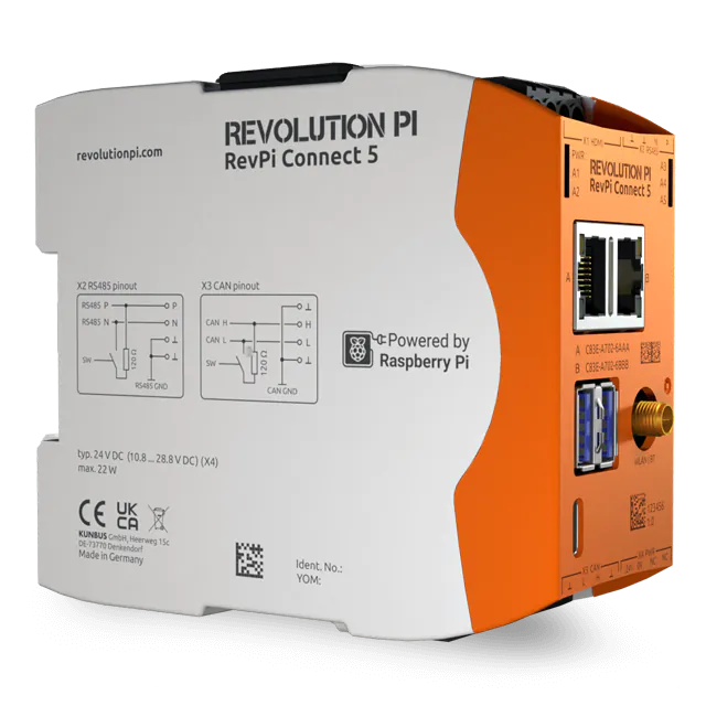
Base Module
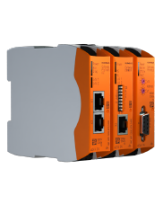
RevPi Connect 5
>>
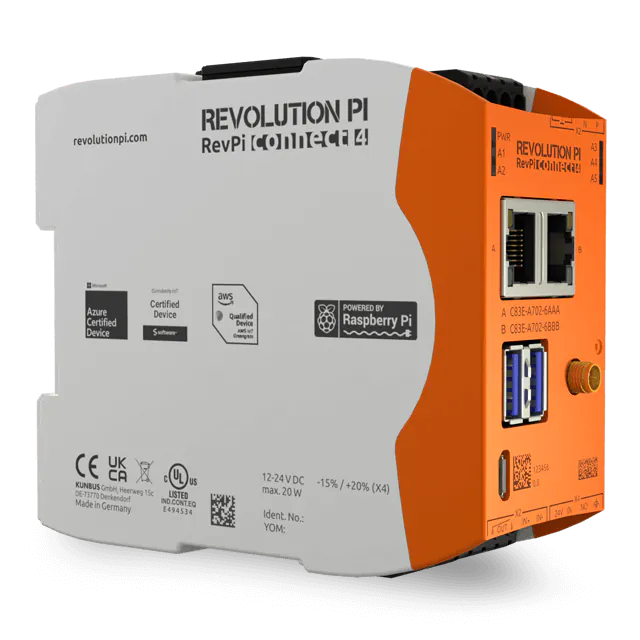
Base Module
RevPi Connect 4
>>
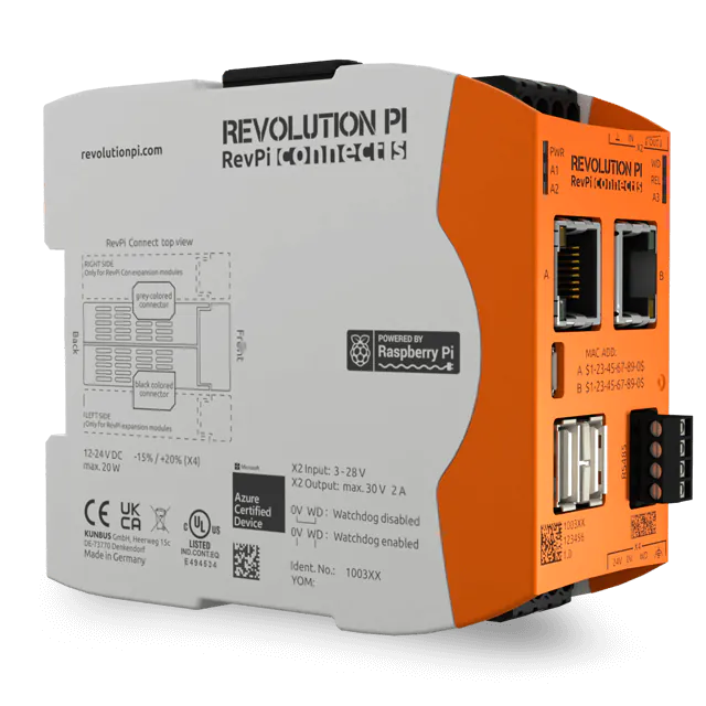
Base Module
RevPi Connect S/SE
>>
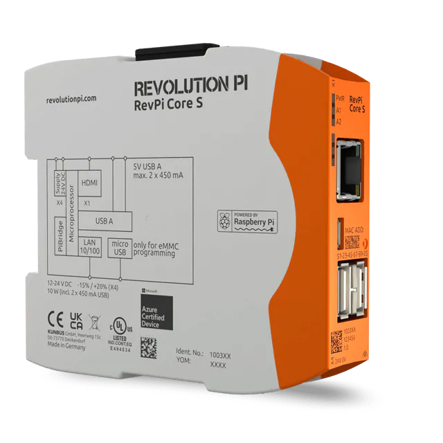
Base Module
RevPi Core S/SE
>>
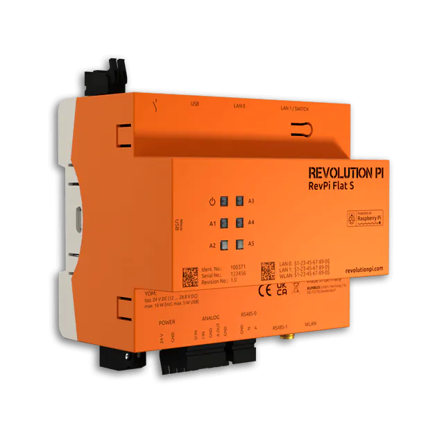
Base Module
RevPi Flat/Flat S
>>
RevPi Expansion Modules #
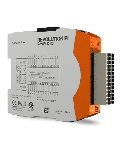
Expansion Module
RevPi DIO
>>
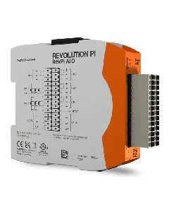
Expansion Module
RevPi AIO
>>
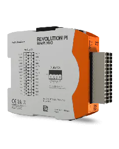
Expansion Module
RevPi MIO
>>
Expansion Module
RevPi DI
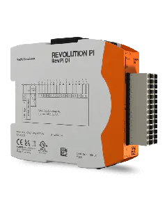
>>
Expansion Module
RevPi DO
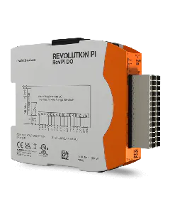
>>
Expansion Module
RevPi RO
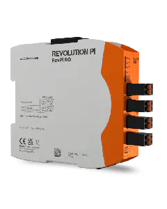
>>
Expansion Modules
RevPi Con Modules

>>
Expansion Modules
RevPi Gateways
>>
Expansion Modules
Virtual Devices
>>
Software #
Software
Operating System Images
>>
Software
RevPi Trixie
>>
Software
RevPi Bookworm
>>
Software
Cockpit
>>
Software
PiCtory
>>
Software
piControl
>>
Software
piTest
>>
Software
CODESYS
>>
Software
Node-RED
>>
Further Resources #
Resources
Data Sheets
>>
Resources
Downloads
>>
Support
Contact
>>
Archive #
-
RevPi Status (Webstatus) – Application for basic configuration of RevPi devices until RevPi Bullseye (04/2024)