Product Description #
The RevPi AIO is an expansion module of the Revolution Pi product family with 4 analog inputs, 2 analog outputs and 2 RTD channels.
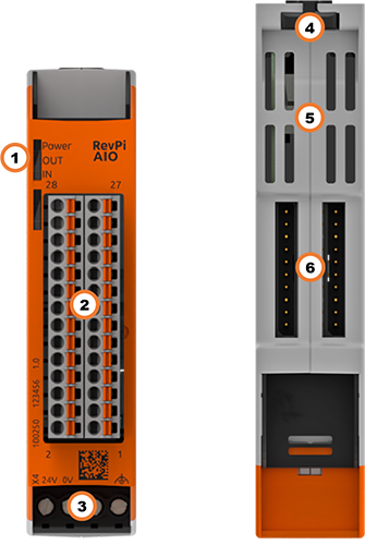
Components #
| Position | Component | Application |
|---|---|---|
1 |
3 × status LED |
|
2 |
6 × analog input |
|
3 |
X4 connector |
|
4 |
Locking clamps |
|
5 |
Ventilation Slots |
|
6 |
2 × PiBridge |
Pinout #
The RevPi AIO has
-
2 analog outputs for current or voltage
-
4 analog inputs for current and voltage
-
2 RTD channels for resistance temperature sensors (Pt100/1000)
The pins on the connector are assigned as follows:
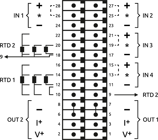
For the configuration, see Configuring RevPi AIO in the PiCtory Value Editor .
LEDs #
The LEDs indicate different device statuses.
Power #
| Signal | Function |
|---|---|
Green |
The connection to the RevPi base module is established. |
Flashes red |
The connection to the RevPi base module is being established (initialization phase). |
Red |
The connection to the RevPi base module is interrupted. |
OUT #
| Signal | Function |
|---|---|
Off |
The connection to the RevPi base module is not yet established (initialization phase). |
Green |
Outputs are ready for operation. |
Flashes red |
Range error. The values of the RevPi base module are too high or too low. |
Red |
Error at the outputs. |
IN #
| Signal | Function |
|---|---|
Off |
The connection to the RevPi base module is not yet established (initialization phase). |
Green |
Inputs are ready for operation. |
Flashes red |
Range error. The voltage or current applied to one or more outputs is too high. |
Compatible Base Modules #
-
RevPi Connect 5
-
RevPi Connect 4
-
RevPi Connect SE (left side only)
-
RevPi Connect+ (left side only)
-
RevPi Connect S (left side only)
-
RevPi Core (all variants)
Scope of Delivery #
The scope of delivery includes
-
RevPi expansion module
-
PiBridge plug connector
-
X4 connector
-
2 × 14-pin I/O module
-
2 × blind plug for PiBridge
-
Supplement
Mounting and Connecting #
The RevPi was developed for use in a control cabinet. Observe the specifications for the Intended Use and all Safety Instructions.
|
Warning
|
Danger to life due to electrical shock
There is a risk of fatal electrical shock when working on devices in the switch cabinet with 230 V mains voltage. ▷ Operations in the switch cabinet may only be carried out by qualified electricians. ▷ Before carrying out any operations in the switch cabinet, switch off the power supply properly. |
Carry out the mounting and connection in the following order:
-
Mount the RevPi base module and all expansion modules on a DIN rail.
-
Connect the expansion module via the PiBridge plug connector.
-
Connect all other devices such as sensors and actuators.
-
As the last step connect the power supply.
Configuration #
The RevPi expansion modules are configured via the System Configuration with PiCtory.
Configuring RevPi AIO in PiCtory #
The RevPi AIO has:
-
2 analog outputs for current or voltage
-
4 analog inputs for current and voltage
-
2 RTD channels for resistance temperature sensors (Pt100/1000)
These can be configured in PiCtory’s Value Editor.
Mind the Pinout.
▷ Start PiCtory.
▷ Insert the RevPi AIO from the Device Catalog > I/O Devices into the correct slot in the Revolution Pi system on the Configuration Board.
▷ If necessary, adjust the basic configuration of the RevPi AIO under Device Data.
▷ Configure the settings in the Value Editor (see below).
▷ Save the configuration via File > Save as Start-Config. .
▷ Restart the driver via Tools > Reset Driver .
Analog Inputs #
The inputs can be set as either voltage or current inputs, e.g. for motion or level sensors with analog outputs (typically 4 … 24 mA or 0 … 10 V).
IN 1 — Input 1 #
| PIN | Usage |
|---|---|
24 |
- negative input for current or voltage measurement channel 1 |
26 |
*a wire bridge must be installed for current measurements from here to pin 28 |
28 |
+ positive input for current or voltage measurement channel 1 |
IN 2 — Input 2 #
| Pin | Usage |
|---|---|
23 |
- negative input for current or voltage measurement channel 2 |
25 |
*a wire bridge must be installed for current measurements from here to pin 27 |
27 |
+ positive input for current or voltage measurement channel 2 |
IN 3 — Input 3 #
| Pin | Usage |
|---|---|
17 |
- negative input for current or voltage measurement channel 3 |
19 |
*a wire bridge must be installed for current measurements from here to pin 21 |
21 |
+ positive input for current or voltage measurement channel 3 |
IN 4 — Input 4 #
| Pin | Usage |
|---|---|
11 |
- negative input for current or voltage measurement channel 4 |
13 |
*a wire bridge must be installed for current measurements from here to pin 15 |
15 |
+ positive input for current or voltage measurement channel 4 |
Input Values in the PiCtory Value Editor #
| Name | Value | Function |
|---|---|---|
Input1Range … Input4Range |
Input range for voltage or current measurement according to the connected sensor, typical for industrial sensors are 0 ... 10 V or 4 ... 24 mA. |
|
ADC_DataRate |
Frequency for data rate on the analog converter for all 4 inputs. |
|
Scaling input 1 ... 4:Input1MultiplierInput1DivisorInput1Offset |
Scaling input channels. |
Status Messages #
Status messages are output on OutputStatus_1 … 2 in the event of an error:
| Bit Position | Status Message |
|---|---|
Bit 0 (LSB) |
0 = value is higher than the lower limit of the configured range. |
Bit 1 |
0 = value is lower than the upper limit of the configured range. |
Analog outputs #
The outputs can either output voltage or current, e.g. for actuators such as frequency converters for speed control.
OUT 1-- Output 1 #
| Pin | Usage |
|---|---|
1 |
V+ positive output for voltage ranges channel 1 |
3 |
I+ positive output for current ranges channel 1 |
5 |
- common ground for both output channels 1 and 2 (current and voltage) |
7 |
- common ground for both output channels 1 and 2 (current and voltage) |
OUT 2 — Output 2 #
| Pin | Usage |
|---|---|
2 |
V+ positive output for voltage ranges channel 2 |
4 |
I+ positive output for current ranges channel 2 |
6 |
- common ground for both output channels 1 and 2 (current and voltage) |
8 |
- common ground for both output channels 1 and 2 (current and voltage) |
Output Values in the PiCtory Value Editor #
| Name | Value | Function |
|---|---|---|
Output1Range |
Off (output inactive) |
Value ranges for current or voltage |
Output1EnableSlew |
On |
Use / do not use slew rate. |
Output1SlewStepSize |
1 |
Increment of the slew rate. |
Output1SlewUpdateFreq |
258 kHz |
Step cycle frequency for the slew rate |
Scaling output 1: |
16 bit signed multiplier |
Scaling output channels. |
Status Messages
Status messages are output on OutputStatus_1 … 2 in the event of an error:
| Bit Position | Status Message |
|---|---|
Bit 0 (LSB) |
Temperature error output module (continuing overload, short circuit) |
Bit 1 |
Open load error current output (connected circuit too high impedance, e.g. cable interrupted) |
Bit 2 |
Internal CRC error output module (e.g. hardware defect, serious external interference signals) |
Bit 3 |
Range Error: The output value in the process image is outside the configured output range. |
Bit 4 |
Reserved for internal purposes |
Bit 5 |
Supply voltage for the expansion module <10.2 V. Outputs have been switched off. |
Bit 6 |
Supply voltage for the expansion module >28.8 V. The outputs have been switched off. |
Bit 7 (MSB) |
Timeout when connecting to the RevPi base module (e.g. PiBridge fault, piControl fault). The outputs have been shut down. |
If the outputs have been switched off for safety reasons, the outputs are re-available only after a restart of the device or a reset of the PiBridge (e.g. piTest -x).
RTD Channels #
The temperature of connected Pt100 and Pt1000 sensors can be determined via the RTD channels.
Mind the Pinout. Pinout
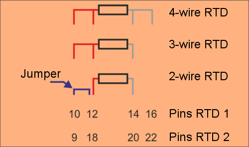
The RevPi AIO uses the 3-wire measuring method for a 2-wire sensor. Therefore, you have to simulate the missing third wire with a wire bridge between pins 10 and 12 and 9 and 18 respectively.
MEM Memory Values in the PiCtory Value Editor #
Specifications for RTD1 apply analogously to RTD2.
| Name | Value | Function |
|---|---|---|
RTD1Type |
Pt100 |
Selecting the sensor type |
RTD1Wiring |
2-Wire |
Selection of measuring method. |
RTD1Multiplier |
16 bit signed multiplier |
Setting scaling for RTD channels. It is determined by means of the three configuration values and calculated in accordance with the following formula from the original value (which exists in 1/10 °C): |
The scaling can subsequently be used for conversion in other units or for a subsequent calibration of a temperature sensor. A 32-bit integer arithmetic is used for calculations in the RevPi AIO. The results are stored as 16-bit values in the process image. Should the result Y exceed the limits of a 16-bit signed value, the fault will be recognised and the value limited. The output values for scaling factor 1 always have to be stored in the process image in the unit mV or µA respectively.
Example #
In order to manage the temperature in °C without decimal places in the process image, the setting must be the following:
Multiplier = 1, Divisor = 10, Offset = 0
In order to manage the temperature in °F in the process image, the parameters have to be set like this:
Multiplier = 18, Divisor = 100, Offset = 32
For process data in °Kelvin you need these values:
Multiplier = 1, Divisor = 10, Offset = 273
Should an error occur, you receive error messages in the input values of the channels RTD_Status_Ch1 and RTD_Status_Ch2. The values have the following meanings:
| Bit Position | Function |
|---|---|
Bit 0 (LSB) |
0 = temperature is higher than -200 °C |
Bit 1 |
0 = temperature is lower than 850 °C |
Should the recorded temperature be outside the range, the respective limit will be issued (-200.0 °C or 850.0 °C) and the respective status bit will additionally be set.
In the fields RTDValue_1 and RTDValue_2 you can define symbolic names for the 4 analog input values. With these names you can read out measured values of the connected sensors from the process image with piTest, a self-written program or an application software. The values are given there in 1/10 °C if you leave the scaling at 1.
Status signals in process image #
To evaluate a fault status of the RevPi AIO precisely, your user software has to evaluate the status entry in the process image. Status entries are stored there as input values from the PiControl driver. The position (offset) in the process image can be gleaned for example from the offset export in PiCtory or inquired via the symbolic name of the respective status values also with the piTest command line tool. The meaning of each individual bit belonging to the status bytes can be found in the table below:
| Bit | Cause | LED signal | Reaction |
|---|---|---|---|
Status signals analog outputs |
|||
Bit 0 (LSB) |
Temperature fault in the output module. The output module has overheated due to being overloaded for a longer period of time (short circuit). |
red steady |
- |
Bit 1 |
Open load fault from the power output. In the "power output" operating mode, the connected circuit is too highly resistive due to, for example, the circuit being interrupted. |
red steady |
- |
Bit 2 |
Internal CRC fault from output module. The fault indicates a hardware defect or serious external interference signal. |
red steady |
- |
Bit 3 |
Range fault: The default value is outside the configurated output range.. |
red flashes |
The output is set to the maximum or minimum permissible value. |
Bit 4 |
Reserved for internal purposes |
- |
- |
Bit 5 |
Supply voltage of the RevPi AIO is below 10.2 V |
red steady |
The outputs are set to 0 as a safe operation cannot be guaranteed. |
Bit 6 |
Supply voltage of the RevPi AIO is over 28.8 V. |
red steady |
The outputs are set to 0 as a safe operation cannot be guaranteed. |
Bit 7 (MSB) |
Time-out in the connection to RevPi Core (e.g. due to a PiBridge error when the piControl drive programm no longer runs properly |
red steady |
The outputs are set to 0. This is the presumable safe state that is also prevalent at the outputs when starting the RevPi AIO. |
Status signals analog inputs |
|||
Bit 0 (MSB) |
Input value is at least 20 mV or 24 µA respectively under the configured input range. |
red flashes |
- |
Bit 1 |
Input value is at least 20 mV or 24 µA respectively over the configured input range. |
red flashes |
- |
Status signals temperature input |
|||
Bit 0 (MSB) |
Measured temperature is below -200 °C or a sensor short circuit. |
- |
- |
Bit 1 |
Measured temperature over 850 °C or a sensor is not connected or the power supply is severed respectively. |
- |
- |