Product Description #
The RevPi Core S or RevPi Core SE is a 24 V industrial PC for IIoT and automation projects based on the Raspberry Pi Compute Module 4S. The RevPi is a base module from the Revolution Pi product family. All devices in the Revolution Pi product family are developed in accordance with EN 61131-2.
Components #
|
Note
|
RevPi Core S and RevPi Core SE have the same structure. |
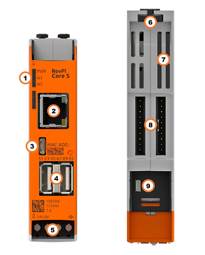
| Position | Component | Application |
|---|---|---|
1 |
3 × status LED |
|
2 |
RJ45 Ethernet |
|
3 |
Micro USB |
|
4 |
2× USB A |
|
5 |
X4 connector |
|
6 |
2 × locking clip |
|
7 |
Ventilation Slots |
|
8 |
2 × PiBridge |
|
9 |
Micro HDMI |
Compatible RevPi Image
-
RevPi Bookworm Image
-
RevPi Bullseye Image
-
RevPi Buster Image
See: RevPi Images.
Variants #
RevPi Core S #
| Item No.: | RAM | eMMC | Compatible with RevPi Gateways |
|---|---|---|---|
100359 |
1 GB |
8 GB |
Yes |
100360 |
1 GB |
16 GB |
Yes |
100361 |
1 GB |
32 GB |
Yes |
RevPi Core SE #
| Item No.: | RAM | eMMC | Compatible with RevPi Gateways |
|---|---|---|---|
100365 |
1 GB |
8 GB |
No |
100366 |
1 GB |
16 GB |
No |
100367 |
1 GB |
32 GB |
No |
For available variants see Revolution Pi Shop.
Expansion Modules #
The RevPi Core S or RevPi Core SE base module can be expanded by up to 10 expansion modules to create a Revolution Pi system:
| Left side | base module | Right side |
|---|---|---|
5 × RevPi I/O module, |
RevPi Core S |
5 × RevPi I/O module, |
5 × RevPi I/O module |
RevPi Core SE |
5 × RevPi I/O module |
Compatible RevPi I/O Modules #
Compatible RevPi Gateways #
RevPi Gateways can only be connected to the system on the far right or far left via a PiBridge plug connector. The RevPi gateways are not supported by the SE models of the Revolution Pi product family.
-
RevPi Gate PROFINET
-
RevPi Gate EtherNet/IP
-
RevPi Gate EtherCAT
-
RevPi Gate PROFIBUS
See RevPi Gateways
Scope of Delivery #
The scope of delivery includes
-
RevPi Core S / RevPi Core SE (base module)
-
X4 connector
-
2 × blind plug for PiBridge/ConBridge
-
Supplement
Mounting and Connecting #
The RevPi was developed for use in a control cabinet. Observe the specifications for the Intended Use and all Safety Instructions.
|
Warning
|
Danger to life due to electrical shock
There is a risk of fatal electrical shock when working on devices in the switch cabinet with 230 V mains voltage. ▷ Operations in the switch cabinet may only be carried out by qualified electricians. ▷ Before carrying out any operations in the switch cabinet, switch off the power supply properly. |
Carry out the mounting and connection in the following order:
-
Mount the RevPi base module and all expansion modules on a DIN rail.
-
Connect the expansion modules via PiBridge plug connectors.
-
If necessary, connect the RevPi Con modules via ConBridge plug connectors.
-
Connect all other devices such as sensors and actuators. The interfaces available to you for this can be found in the Structure section.
-
Connect a monitor and a keyboard if you want to operate the RevPi in Desktop Mode. This is not necessary if you access the RevPi via a network connection.
-
As the last step connect the power supply.
|
Note
|
The RevPi Gateways are not supported by the RevPi SE models. |
Access to the Device #
The RevPi is accessed in two steps:
Install all available Updates as soon as the RevPi is connected to the internet, so that the system is always up to date with security-relevant features.
Alternatively, access is possible without a network, see Desktop Mode.
See also:
Configuration #
Basic Configuration #
From the RevPi Bookworm Image (10/2024) onwards, the basic configuration of the RevPi devices is carried out via the Cockpit web application.
Until the RevPi Bullseye Image (04/2024), the basic configuration of the RevPi devices is carried out via the RevPi Status web application.
System Configuration #
The Revolution Pi system, i.e. a RevPi base module with expansion modules, is configured via the PiCtory web application.
Configuring the Base Module in PiCtory #
▷ Start PiCtory.
▷ Select the RevPi base module from the Device Catalog and drag and drop it onto the empty slot with position number 0.
❯ The configurable values appear in the Value Editor.
▷ Save the configuration as the start configuration with File > Save as Start-Config.
❯❯ The start configuration is called up directly after each boot process.
| Value | Function |
|---|---|
INP RevPiStatus |
Status of the piControl driver |
INP RevPiIOCycle |
Cycle time of PiBridge communication between base module and expansion modules in ms |
INP RS485ErrorCnt |
Error counter for PiBridge communication |
INP Core_Temperature |
CPU temperature |
INP Core_Frequency |
CPU frequency |
OUT RevPiLED |
Status byte for LEDs |
OUT RS485ErrorLimit1 |
First limit value for error counter > Message in kern.log |
OUT RS485ErrorLimit2 |
Second limit value for error counter > PiBridge communication is stopped |
Ethernet Interface #
The RevPi has a 10/100 Ethernet connection (RJ45). This allows the RevPi to be connected to a network.
The MAC address is printed on the front of the housing.
Under Linux, the interface can be addressed with eth0.
USB Interfaces #
The RevPi has two USB-A Interfaces. This allows USB 2.0 client devices such as USB hard disks, surf sticks, keyboards or mice to be connected. Each socket may be loaded with a maximum of 500 mA. If more than two USB-A ports are required, a USB hub can be connected.
LEDs #
LED PWR
The PWR (Power) LED indicates the device status.
| Signal | Function |
|---|---|
Green |
Power supply is connected. |
Red |
There is a communication fault between connected modules. |
LED A1 and A2
LEDs A1 and A2 are customizable.
The LEDs can be used for user-specific requirements such as indicating a network connection, indicating that a memory limit has been exceeded, monitoring a process and indicating faults.
The LEDs can be switched in the command line application piTest with the variable RevPiLED.
The RevPiLED output has a defined byte length and therefore has a certain number of bits that are read from right to left. Certain bit positions are each assigned to an LED. The LED is switched by setting the respective bits to 0 or 1.
| LED | Assigned bit position |
|---|---|
A1 |
0 and 1 |
A2 |
2 and 3 |
An LED signal is set in the command line with the command piTest -w RevPiLED,x where x corresponds to the decimal value calculated from the respective bit pattern.
| LED | Signal |
|---|---|
Bit pattern |
Decimal value |
A1 … A2 |
off |
0000 |
0 |
A1 |
green |
0001 |
|
1 |
|
red |
0010 |
2 |
orange |
0011 |
3 |
A2 |
green |
0100 |
|
4 |
|
red |
1000 |
8 |
orange |
1100 |
12 |
To switch several LEDs simultaneously, the respective decimal values have to be added up.
Example: If LED A1 shall flash red and LED A2 green at the same time, the command is piTest -w RevPiLED,6 (bit pattern: 0000 0110 = decimal values 2+4).
|
Note
|
If a signal is to be added to an existing LED circuit, the value for all required signals must be recalculated and rewritten. |