In this tutorial, you will learn how to use Node-RED to control a LED connected to the output of a RevPi DIO, connected with a RevPi Connect 4. The tutorial is designed for users familiar with basic programming and IoT concepts who want to integrate hardware and software using industrial-grade components.
The focus will be on:
-
Setting up a Node-RED flow.
-
Switching a LED on and off via a web-based Node-RED dashboard.
Prerequisites #
Hardware #
-
RevPi Connect 4
-
A 12V LED
-
Connection cables (for wiring the RevPi DIO and the LED).
Software #
-
Node-RED
If you are using the full image, Node-RED is already pre-installed. If you are using the lite image, Node-RED is not pre-installed. You can install Node-RED according to the instructions at the following link: Running on Raspberry Pi: Node-RED.
-
Web browser (for accessing the Node-RED interface and PiCtory)
System Setup #
Follow these steps to configure your system. For detailed instructions, refer to the Getting Started guide.
-
Power Up the RevPi Connect 4
▷ Connect the RevPi Connect 4 to a power source.
▷ Ensure it is connected to your local network for accessibility.
-
Power Up the RevPi DIO
▷ Power on the RevPi DIO.
-
Verify Connections
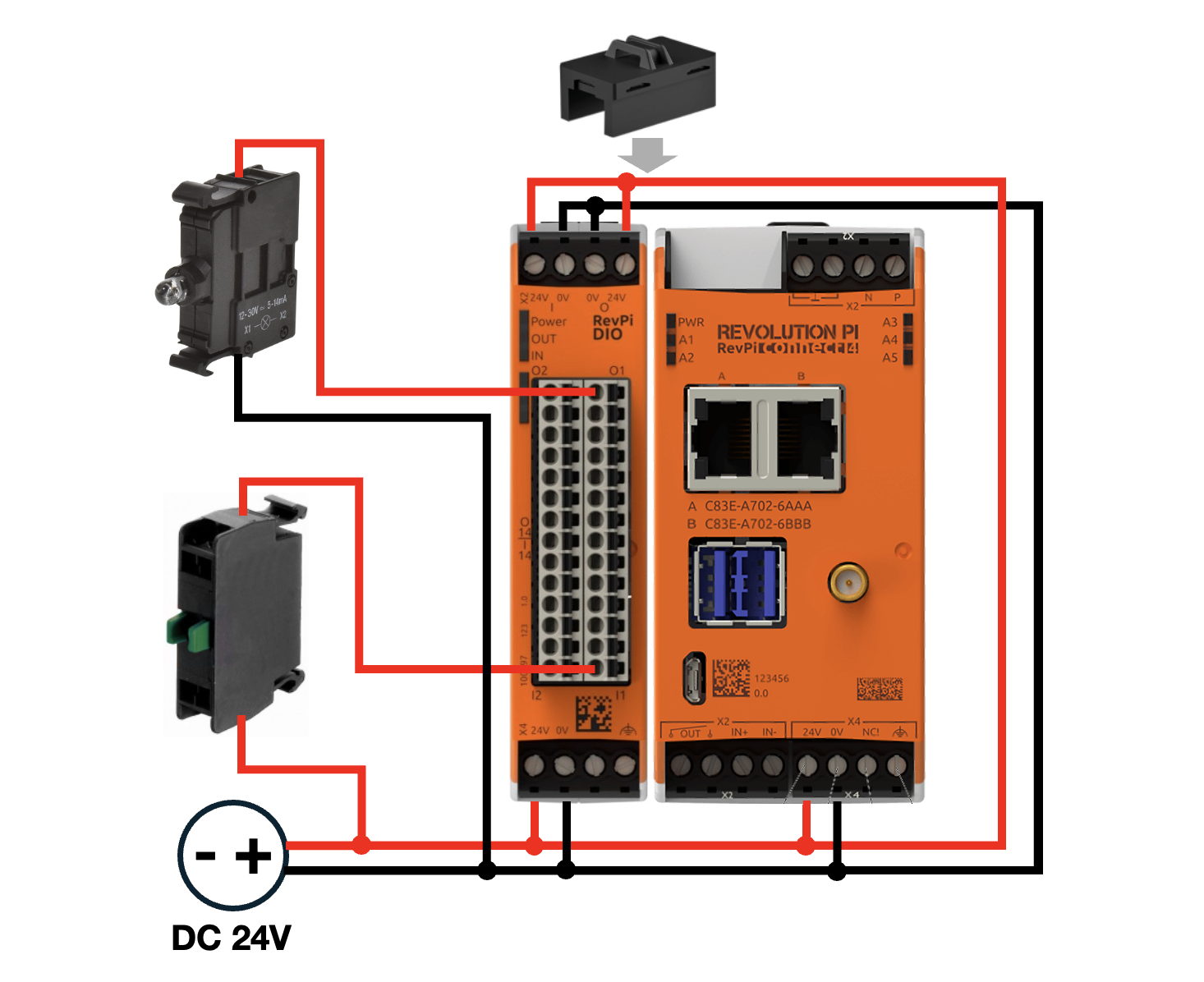
▷ Check that the 12V LED is properly connected to the RevPi DIO.
▷ Ensure the RevPi DIO is securely connected to the RevPi Connect 4 via the PiBridge interface.
-
Access the RevPi Interface
▷ Open a web browser on a device connected to the same network.
▷ Access the RevPi system using its IP address.
|
Note
|
For network troubleshooting or determining the IP address of your RevPi, consult the Getting Started guide. |
Step 1: Configure the Hardware in PiCtory #
Step 2: Create a Basic Flow in Node-RED #
▷ Run the following command on Terminal to install the package:
npm install node-red-dashboard▷ Add a Dashboard switch Node:
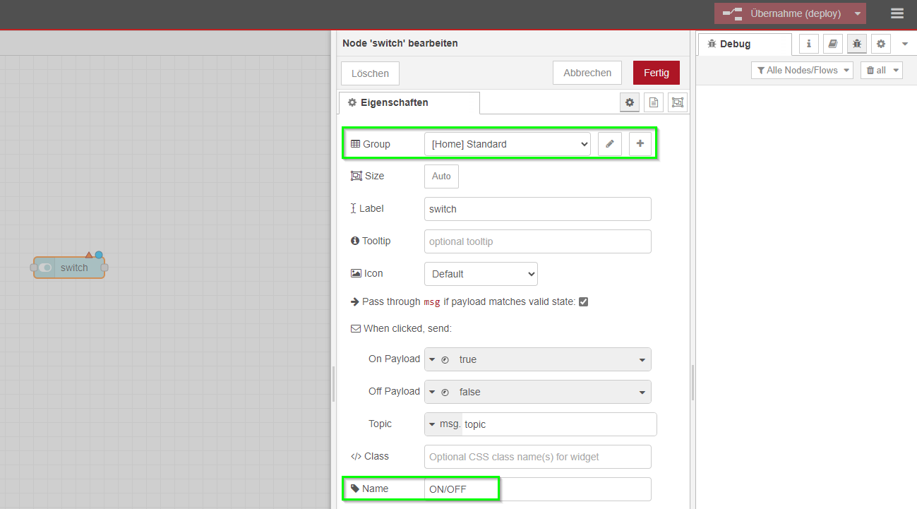
Use the Node-RED interface to add a switch node to toggle the LED state.
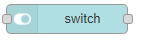
▷ Double-click the switch Node node to configure them.
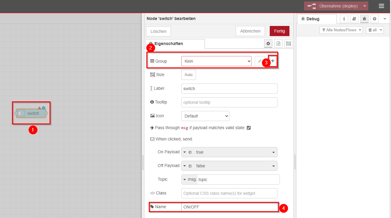
After configuration:
The Revolution Pi palette provides a set of nodes in Node-RED to read and write I/O pins of the Revolution Pi system.
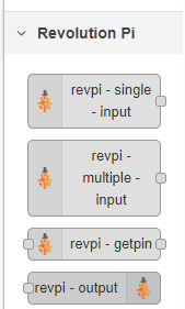
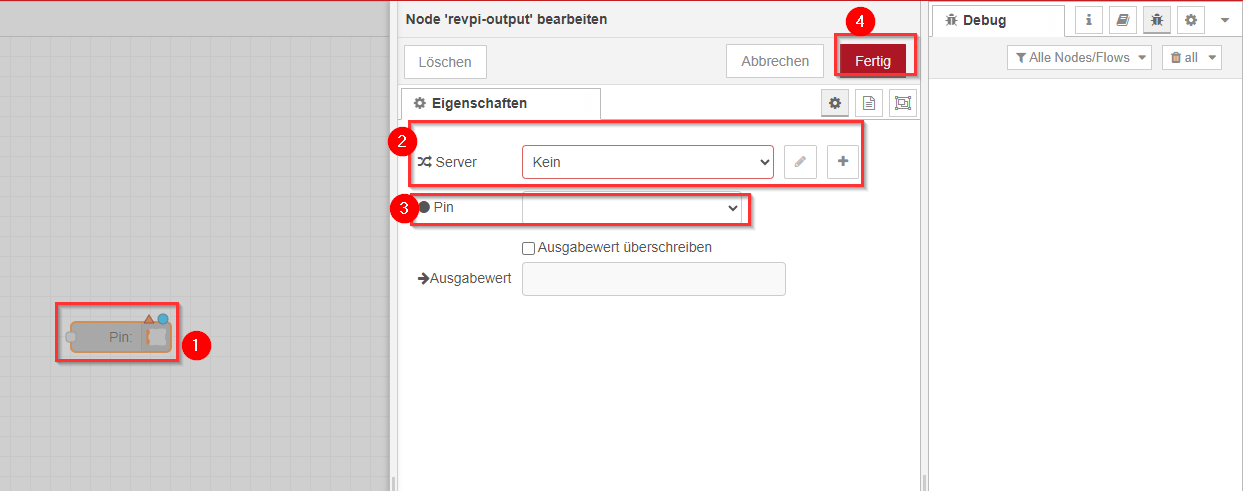
▷ Drag and drop the revpi-output
▷ Double-click the nodes to configure them.
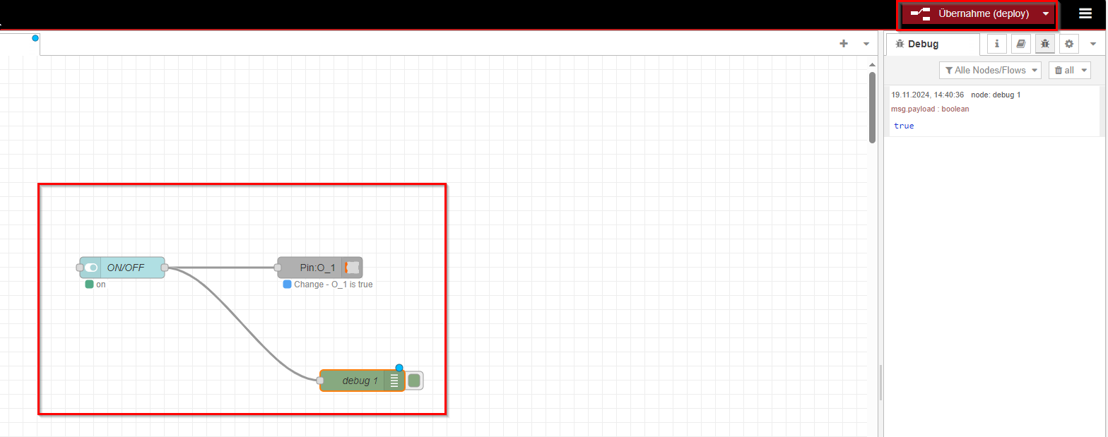
After configuration:
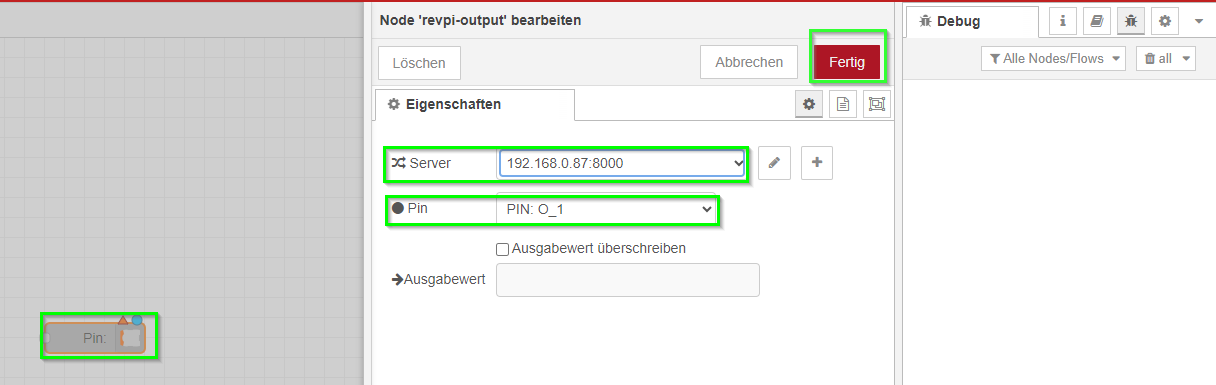
For the configuration of the RevPi module nodes, you must enter a server and a pin. After entering the server (in the format <IP address>:8000), you should automatically be able to select a pin depending on the type of node, whether it is an input or output. In this case, you want to use Output 1 (named Output_LED) of the RevPi DIO.
▷ Drag and drop the debug node
The role of this node is to display debugging information and help you troubleshoot by showing messages flowing through the flow.
▷ Deploy your Node-RED flow by clicking the Deploy button in the top-right corner of the interface. This will activate the flow
Step 3: Quick Test with Prebuilt Flow #
If you prefer to test the flow without manually creating it step by step, you can directly import the JSON export provided below. This flow includes all the necessary nodes to toggle the LED state and visualize the payload in the Debug sidebar.
Prerequisite #
Before importing the JSON, make sure that the Node-RED Dashboard package is installed. If not, install it by running the following command in your RevPi terminal:
npm install node-red-dashboardImport the Prebuilt Flow* #
-
Copy the JSON export below:
[ { "id": "45371098831c2f50", "type": "tab", "label": "Flow 1", "disabled": false, "info": "", "env": [] }, { "id": "dd91c103fca0df54", "type": "ui_switch", "z": "45371098831c2f50", "name": "ON/OFF", "label": "switch", "tooltip": "", "group": "c5aa454786599927", "order": 0, "width": 0, "height": 0, "passthru": true, "decouple": "false", "topic": "topic", "topicType": "msg", "style": "", "onvalue": "true", "onvalueType": "bool", "onicon": "", "oncolor": "", "offvalue": "false", "offvalueType": "bool", "officon": "", "offcolor": "", "animate": false, "className": "", "x": 340, "y": 300, "wires": [ [ "b97624cf8482ce4c", "76cf80f93d913ac5" ] ] }, { "id": "b97624cf8482ce4c", "type": "revpi-output", "z": "45371098831c2f50", "server": "23bf8ad0f3c174d6", "outputpin": "O_1", "overwritevalue": false, "outputvalue": "", "x": 620, "y": 300, "wires": [] }, { "id": "76cf80f93d913ac5", "type": "debug", "z": "45371098831c2f50", "name": "debug 1", "active": true, "tosidebar": true, "console": false, "tostatus": false, "complete": "false", "statusVal": "", "statusType": "auto", "x": 680, "y": 460, "wires": [] }, { "id": "c5aa454786599927", "type": "ui_group", "name": "Standard", "tab": "dfde44665fc52d64", "order": 1, "disp": true, "width": "6", "collapse": false, "className": "" }, { "id": "23bf8ad0f3c174d6", "type": "revpi-server", "host": "<your IP_address>", "port": "8000", "user": "pi", "password": "8e62gy", "rejectUnauthorized": false, "ca": "" }, { "id": "dfde44665fc52d64", "type": "ui_tab", "name": "Home", "icon": "dashboard", "disabled": false, "hidden": false } ] -
Open the Node-RED editor on your RevPi by navigating to:
http://<revpi_ip_address>:1880 -
In the editor:
-
Click the menu (☰) in the top-right corner.
-
Select Import > Clipboard.
-
Paste the JSON code into the import window and click Import.
-
-
Place the imported nodes on the workspace and click Deploy to activate the flow.
Test the Flow #
▷ Open the Node-RED Dashboard in your web browser:
http://<revpi_ip_address>:41880/ui
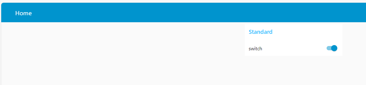
▷ Use the ON/OFF toggle switch in the dashboard to test:
-
Toggling the switch sends a Boolean value (
trueorfalse) to the Pin: O_1 node, which simulates the LED state.
-
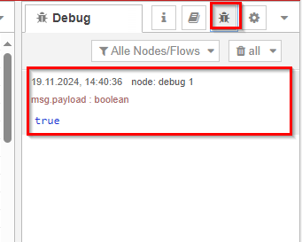
The payload is displayed in the Debug sidebar of the Node-RED editor.