Product Description #
The RevPi RO is an expansion module from the Revolution Pi product family and has 4 relay outputs, e.g. to connect or disconnect the power supply for connected hardware.
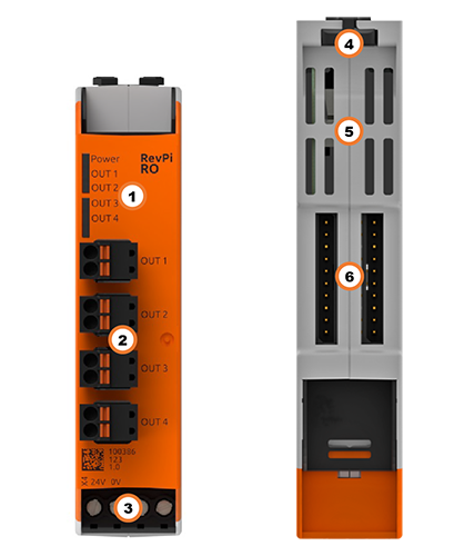
Components #
| Position | Component | Application |
|---|---|---|
1 |
5 × status LED |
|
2 |
4 × relay output |
|
3 |
X4 connector |
|
4 |
Locking clamp |
|
5 |
Ventilation Slots |
|
6 |
2 × PiBridge |
LEDs #
The LEDs indicate different device statuses.
Power
| Signal | Function |
|---|---|
Green |
The connection to the RevPi base module is established. |
Flashes red |
The connection to the RevPi base module is being established (initialization phase). |
Red |
The connection to the RevPi base module is interrupted. |
OUT 1 - 4
| Signal | Function |
|---|---|
Green |
Relay is switched on. |
Flashes red/ green |
Warning limit for switching operations is reached (relay is switched on). |
Red |
Warning limit for switching operations is reached (relay is switched off). |
Compatible Base Modules #
-
RevPi Connect 5
-
RevPi Connect 4
-
RevPi Connect SE (left side only)
-
RevPi Connect+ (left side only)
-
RevPi Connect S (left side only)
-
RevPi Core (all variants)
Scope of Delivery #
The scope of delivery includes
-
RevPi expansion module
-
PiBridge plug connector
-
X4 connector
-
4 × 2-pin plug for relay contacts
-
2 × blind plug for PiBridge
-
Supplement
Mounting and Connecting #
The RevPi was developed for use in a control cabinet. Observe the specifications for the Intended Use and all Safety Instructions.
|
Warning
|
Danger to life due to electrical shock
There is a risk of fatal electrical shock when working on devices in the switch cabinet with 230 V mains voltage. ▷ Operations in the switch cabinet may only be carried out by qualified electricians. ▷ Before carrying out any operations in the switch cabinet, switch off the power supply properly. |
Carry out the mounting and connection in the following order:
-
Mount the RevPi base module and all expansion modules on a DIN rail.
-
Connect the expansion module via the PiBridge plug connector.
-
Connect all other devices such as sensors and actuators.
-
As the last step connect the power supply.
Configuration #
The RevPi expansion modules are configured via the System Configuration with PiCtory.
Configuring RevPi RO in PiCtory #
For the RevPi RO relay output expansion module, the 4 relay outputs OUT1 to OUT4 can be configured via PiCtory in the Value Editor.
▷ Start PiCtory.
▷ Insert the RevPi RO from the Device Catalog > I/O Devices into the correct slot in the Revolution Pi system on the Configuration Board .
▷ If necessary, adjust the basic configuration of the RevPi RO under Device Data.
▷ In the Value Editor configure the settings (see below).
▷ Save the configuration via File > Save as Start-Config..
▷ Restart the driver via Tools > Reset Driver.
MEM Memory Values #
You can use the four memory variables in the (MEM) Value Editor to be set a threshold value for the number of switching operations for each relay output. If this threshold value is exceeded, the RevPi RO switches on the red status LED for the respective output and generates a warning at the status bit for the respective relay.
The default value is 0. A threshold value of 0 generates no warning at the status bit and the status LED is not triggered.
Recommended threshold values according to the data sheet of the relay module used:
| Type of load | Voltage | Current | Recommended threshold value for warning limit |
|---|---|---|---|
Resistive load |
250 V AC |
3 A |
100 000 |
30 V DC |
100 000 |
||
250 V AC |
5 A |
80 000 |
|
30 V DC |
80 000 |
||
Inductive load |
250 V AC |
2 A |
100 000 |
30 V DC |
100 000 |
||
No load |
0 V |
0 A |
1 000 000 |
You can query the current number of switching operations with piTest -C RO-ADDRESS.
Status Byte in the Process Image #
Status |
Offset: 0 |
Bits 0 … 3 show the current warning status of relays OUT1 … OUT4: |