Here you will find the most important steps to get your RevPi up and running.
▷ Observe the specifications for the intended use.
▷ Familiarize yourself with the safety instructions before commissioning.
Mounting and Connecting #
The RevPi was developed for use in a control cabinet. Observe the specifications for the intended use.
|
Warning
|
Danger to life due to electrical shock
There is a risk of fatal electrical shock when working on devices in the switch cabinet with 230 V mains voltage. ▷ Operations in the switch cabinet may only be carried out by qualified electricians. ▷ Before carrying out any operations in the switch cabinet, switch off the power supply properly. |
Carry out the installation and connection in the following order:
-
Mount the RevPi base module and all expansion modules on a DIN rail.
-
Connect all expansion modules via PiBridge plug connectors.
-
If necessary, connect the RevPi Con modules via ConBridge plug connectors.
-
Connect all other devices such as sensors and actuators. The interfaces that are available to you for this can be found in the respective section Structure of your RevPi base module or the RevPi expansion modules.
-
Connect a monitor and a keyboard if you want to operate the RevPi in desktop mode. This is not necessary if you access the RevPi via a network connection.
-
Finally, connect the power supply.
Mounting the Device on a DIN Rail #
|
Important
|
Damage to the device due to overheating
The ambient temperature in the switch cabinet must not exceed the maximum permissible operating temperature. ▷ Keep ventilation slots clear. ▷ Observe the installation clearances. ▷ Mount the device in the intended orientation. ▷ Do not place appliances with high input power directly next to each other. ▷ Regularly remove dust and dirt from the area around the appliance. |
You require:
✓ A switch cabinet with DIN rail 35 × 7.5 mm in accordance with DIN EN 60715 (TH35)
✓ A small slotted screwdriver
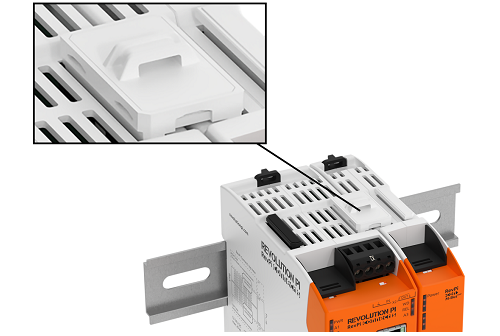
▷ Use the slotted screwdriver to open the black locking clips on the back of the RevPi housing.
▷ Hold the RevPi with the back against the DIN rail.
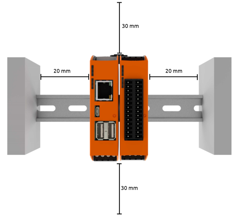
▷ Observe the installation distances:
-
Min. 20 mm to the right and left
-
Min. 30 mm upwards and downwards
▷ Close the locking clips.
▷ Check whether the RevPi is firmly connected to the DIN rail.
Connecting Expansion Modules #
|
Important
|
Damage to the device due to installation under voltage supply
While the RevPi device is connected to a power source, no other devices may be connected or disconnected, as this may cause damage to the devices. ▷ Do not connect the power supply until all other devices are connected correctly. ▷ Switch off the power supply before disconnecting a device from the system. |
|
Important
|
Damage to the device due to different grounding
▷ Refer all connections to the same system ground. ▷ Connect external voltage inputs or outputs with different grounding externally. |
|
Important
|
Damage to the devices due to mix-up of the plug connectors
▷ Only connect RevPi I/O modules and RevPi gateways to the system via the black PiBridge plug connectors. ▷ Only connect RevPi Con M-Bus and RevPi Con CAN to the system via the gray ConBridge plug connectors. |
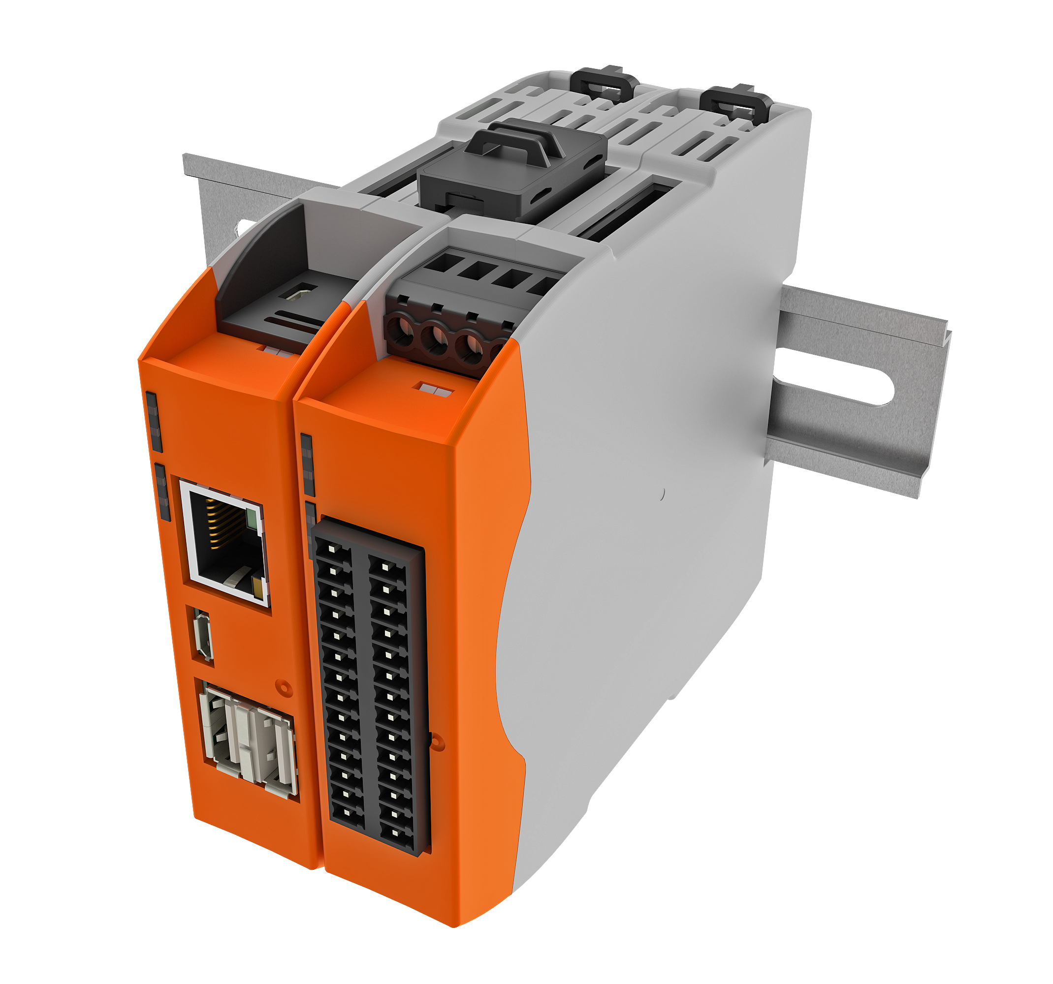
The RevPi I/O modules and RevPi Gateways are connected to the respective neighboring module via PiBridge plug connectors. The PiBridge is a backplane bus via which all data is transmitted from module to module via a signal line. A PiBridge plug connector is included with the expansion module or can be ordered from the store (item no. 100204).
▷ Make sure that all devices are disconnected from their respective power supplies.
▷ Observe the Rules for the Arrangement of Devices.
▷ Mount all RevPi devices next to each other on the DIN rail.
▷ Connect the RevPi devices with the black PiBridge plug connector on the top of the housing.
Rules for the Arrangement of Devices #
The RevPi base module forms the starting point for a Revolution Pi system and determines possible expansion modules.
| Left side | base module | Right side |
|---|---|---|
5 × RevPi I/O module, |
RevPi Connect 5 |
5 × RevPi I/O module, |
5 × RevPi I/O module |
RevPi Connect 4 |
5 × RevPi I/O module |
5 × RevPi I/O module |
RevPi Connect SE |
1 × RevPi Con CAN, |
5 × RevPi I/O module, |
RevPi Connect+ |
1 × RevPi Con CAN, |
5 × RevPi I/O module, |
RevPi Core 3 |
5 × RevPi I/O module, |
5 × RevPi I/O module |
RevPi Core SE |
5 × RevPi I/O module |
- |
RevPi Compact |
- |
Connecting RevPi Con Modules #
|
Important
|
Damage to the device due to installation under voltage supply
While the RevPi device is connected to a power source, no other devices may be connected or disconnected, as this may cause damage to the devices. ▷ Do not connect the power supply until all other devices are connected correctly. ▷ Switch off the power supply before disconnecting a device from the system. |
|
Important
|
Damage to the devices due to mix-up of the plug connectors
▷ Only connect RevPi I/O modules and RevPi gateways to the system via the black PiBridge plug connectors. ▷ Only connect RevPi Con M-Bus and RevPi Con CAN to the system via the gray ConBridge plug connectors. |
The RevPi Con modules are connected to a RevPi Connect base module via gray ConBridge plug connectors and supplied with power. A plug connector is included in the scope of delivery of a RevPi Con module or can be ordered via the store (item no. 100297).
RevPi Con modules can only be connected on the right-hand side of the following base modules.
| Left side | Base module | Right side |
|---|---|---|
5 × RevPi I/O module |
RevPi Connect SE |
1 × RevPi Con CAN, |
5 × RevPi I/O module, |
RevPi Connect+ |
1 × RevPi Con CAN, |
▷ Mount the RevPi Con module to the right of the RevPi Connect on the DIN rail.
▷ Connect the RevPi devices with the gray ConBridge plug connector on the top of the housing.
Connecting the Power Supply #
|
Warning
|
Danger to life due to electrical shock
There is a risk of fatal electrical shock when working on devices in the switch cabinet with 230 V mains voltage. ▷ Operations in the switch cabinet may only be carried out by qualified electricians. ▷ Before carrying out any operations in the switch cabinet, switch off the power supply properly. |
|
Important
|
Damage to the device due to impermissible power supply
▷ Observe the maximum voltage supply of 28.8 V DC. ▷ Only use the supplied plug and a suitable power supply unit. ▷ Ensure correct polarity when connecting. ▷ Ensure a stable power supply. |
|
Important
|
Damage to the device due to installation under voltage supply
While the RevPi device is connected to a power source, no other devices may be connected or disconnected, as this may cause damage to the devices. ▷ Do not connect the power supply until all other devices are connected correctly. ▷ Switch off the power supply before disconnecting a device from the system. |
|
Important
|
Damage to the device due to different grounding
▷ Refer all connections to the same system ground. ▷ Connect external voltage inputs or outputs with different grounding externally. |
Wiring via the power connector (X4) is required for the power supply.
You require:
✓ One power supply unit (see maximum power consumption in the data sheet)
✓ Cable with cross-section 0.35 … max. 2.5 mm²
✓ Stripping and crimping pliers
✓ If you use stranded wire, apply suitable wire end sleeves
✓ A small slotted screwdriver
▷ Disconnect all connected devices from their respective power supply.
▷ Connect a supply for the power supply of typ. 24 V DC (10.8 … 28.8 V DC) to the pin marked 24V.
▷ Connect the 0 V supply to the pin marked 0 V.
▷ Optional: connect the functional earth (FE) to the correspondingly marked pin:

▷ Check all connected devices for correct polarity.
▷ Switch on the power supply unit.
❯❯ The RevPi starts the boot process.
Access to the Device #
The RevPi is accessed in two steps:
Alternatively, access without a network is possible, see Desktop Mode.
Establishing a Network Connection #
|
Important
|
Security risk due to network connection
The device may be accessed without authorization via the Internet if a network connection is established. ▷ Secure the network connection. ▷ Change the specified password after the first login on the device. ▷ Use a strong password. ▷ Access via the network only from known devices. |
To be able to access the RevPi base module, you must connect it to a network.
▷ Connect the power supply to the RevPi base module.
▷ Connect the RevPi to a DHCP-capable router using an Ethernet cable at the RJ-45 socket.
❯❯ The network connection is established.
❯❯ If the DHCP router is connected to the Internet and no router settings prohibit a connection, the RevPi is also connected to the Internet.
Identifying the IP Address #
If the RevPi is connected to a DHCP-capable router, it is automatically assigned an IP address in the network by the router.
From the RevPi Bookworm Image (10/2024) onwards, you can call up the IP address via Cockpit in the Networking menu.
Alternatively, you can determine the IP address using an IP scanner, e.g. with the Advanced IP Scanner tool.
If several RevPi base modules are connected to the network, identify the device using the MAC address printed on the front of the device.
Assigning Static IP Address (without DHCP) #
To connect the RevPi to a network without DHCP, a static IP address must be configured for the device.
Cockpit
From the RevPi Bookworm Image (10/2024) onwards, network settings can be configured via the web application Cockpit.
▷ Start Cockpit.
▷ Click on Networkingin the menu.
▷ Click on the network used under Interfaces.
▷ Click on editunder IPv4 or IPv6.
▷ Select the Manual option under Addresses.
▷ Under Address, define a static IP in the format 255.255.255.0:
Example: 192.168.1.100
▷ Define the subnet mask under Prefix length:
Example: 24
▷ Configure the IP address of the router under Gateway:
Example: 192.168.1.1
▷ Save the connection and restart the RevPi.
NetworkManager
From the RevPi Bullseye Image (06/2023) onwards, the NetworkManager-tui (nmtui) tool is used for this purpose.
▷ Connect directly to the RevPi with keyboard and screen (see Desktop Mode)
or first establish a network connection via DHCP and log in via a terminal.
▷ Start the NetworkManager in the terminal with:
sudo nmtui▷ Create a new connection via the NetworkManager:
-
Type:
Ethernet -
Device:
eth0oreth1 -
IPv4 Configuration:
Manual
▷ Under Addresses, define a static IP in the format 255.255.255.0 and subnet mask /24:
Example: 192.168.1.100/24
▷ Configure the IP address of the router under Gateway:
Example: 192.168.1.1
▷ Configure the DNS server address under DNS servers:
Example: 192.168.1.1
▷ Save the connection and restart the RevPi.
For more information on NetworkManager-tui, see docs.redhat.com.
Login on the Device #
|
Important
|
▷ Change the default password after the first login to the device to prevent unauthorized access. ▷ Use a strong password. |
-
Option 1: Login via Web Browser
-
Option 2: Login via Terminal
-
Option 3: Login via FTP Client
Login via Web Browser #
If the RevPi base module and your PC are in the same network, you can access the RevPi via a web browser.
Login via Cockpit
From the RevPi Bookworm Image (10/2024), login is via the Cockpit web application.
▷ Establish a network connection between the RevPi and your PC.
▷ Open a web browser.
▷ Call up Cockpit via the web browser with revpi[serial number].local
You can find the serial number of the RevPi on the front of the housing next to the QR code.
Alternatively, you can enter the IP address of the RevPi in the web browser.
❯ The warning NET::ERR_CERT_AUTHORITY_INVALID may appear in the browser.
▷ Accept the security exception to continue with the login.
❯ The login screen for Cockpit appears.
▷ Log in with user name pi and the device password.
You will find the device password on the sticker on the side of the RevPi housing.
❯ Cockpit opens in Limited access mode.
▷ Select Limited access in the top main navigation bar to switch to Administrative access mode. You can only configure the RevPi with the elevated rights of this administrative access.
▷ Select RevPi Configuration in the menu to open the RevPi dashboard.
For details, see Basic Configuration with Cockpit.
Login via RevPi Status
Up to the RevPi Bullseye Image (04/2024), login is via the RevPi Status web application, also known as Webstatus.
▷ Establish a network connection between the RevPi and your PC.
▷ Open a web browser.
▷ Call up RevPi Status via the web browser with revpi[serial number].local
You will find the serial number of the RevPi on the front of the housing next to the QR code.
Alternatively, you can enter the IP address of the RevPi in the web browser.
❯ The warning NET::ERR_CERT_AUTHORITY_INVALID may appear in the browser.
▷ Accept the security exception to continue with the login.
❯ The login screen for RevPi Status appears.
▷ Log in with the user name admin and the device password.
▷ Log in with the user name admin and the device password.
You will find the device password on the sticker on the side of the RevPi housing.
For details, see Basic Configuration with RevPi Status.
Login via Terminal #
Some work steps require access to the RevPi base module directly via a terminal.
Option 1: Establishing SSH connection via terminal
▷ Establish a network connection between the RevPi and your PC.
▷ Open a terminal on your PC, e.g. Windows 10/11 command prompt, PowerShell, Linux terminal etc.
▷ Establish an SSH connection with the command ssh pi@revpi[serial number].local.
The serial number is located on the front of the housing next to the QR code.
▷ Log in with user name pi and the device password.
You will find the device password on the sticker on the side of the RevPi housing.
Option 2: Opening terminal via Cockpit
From the RevPi Bookworm Image (10/2024) onwards, an integrated terminal can be opened directly via Cockpit.
▷ Start Cockpit.
▷ Click on Terminal in the menu.
Option 3: Using SSH client
Alternatively, the connection can be established via an SSH client.
▷ Establish a network connection between the RevPi and your PC.
▷ Install and open an SSH client on your PC, e.g. PuTTY, OpenSSh etc.
▷ Enter the parameters for the SSH connection:
-
Port: 22
▷ Start the SSH connection.
❯ An SSH terminal opens.
▷ Log in with user name pi and the device password.
You will find the device password on the sticker on the side of the RevPi housing.
Login via FTP Client #
The login via an FTP client is useful for data transfer between your PC and the RevPi, e.g. to back up data before an update.
▷ Establish a network connection between the RevPi and your PC.
▷ Install and open an FTP client on your PC, e.g. FileZilla, Cyberduck etc.
▷ Enter the parameters for the server connection:
-
Username: pi
-
Password: The device password can be found on the sticker on the side of the RevPi housing.
-
Port: 22 (standard for SFTP)
▷ Start the connection setup.
Setting up Desktop Mode #
In desktop mode, the RevPi base module is connected directly to a monitor, a mouse and a keyboard.
In desktop mode, the RevPi does not necessarily have to be connected to a network. It is not possible to install updates without a network or Internet connection.
|
Note
|
Desktop mode is not possible for the RevPi Flat and RevPi Flat S base modules. |
▷ Make sure that all devices are disconnected from their respective power supplies.
▷ Connect a screen to the micro HDMI interface of the RevPi.
▷ Connect the mouse and keyboard to the USB interfaces of the RevPi.
▷ Connect the power supply to the RevPi.
❯ The RevPi starts the boot process. The terminal appears on the screen.
▷ Log in with user name pi and the device password.
You will find the device password on the sticker on the side of the RevPi housing.
Rebooting RevPi #
|
Important
|
Damage to the device software due to disconnection from the power supply
If the device is disconnected from the power supply during operation, the file system of the eMMC memory may be destroyed. The device can then no longer be booted. ▷ Shut down the device properly before disconnecting it from the power supply. |
Restarting RevPi via Cockpit
▷ Start Cockpit.
▷ Click on Overview in the menu to open the start page for Cockpit.
▷ Click the Reboot button.
▷ Select a Delay for the reboot.
▷ Click the Reboot button.
❯ The RevPi is shut down and will reboot. The power LED flashes red.
❯ The power LED lights up green as soon as the RevPi is ready for operation.
▷ Click the Reconnect button.
❯❯ The login screen for Cockpit appears.
Restarting RevPi via terminal
▷ Log in to the RevPi via a terminal.
▷ Enter the following command:
sudo reboot❯ The RevPi restarts.
▷ Log in with user name pi and the device password.
You will find the device password on the sticker on the side of the RevPi housing.
Shutting Down RevPi #
|
Important
|
Damage to the device software due to disconnection from the power supply
If the device is disconnected from the power supply during operation, the file system of the eMMC memory may be destroyed. The device can then no longer be booted. ▷ Shut down the device properly before disconnecting it from the power supply. |
Shutting down RevPi via Cockpit
▷ Start Cockpit.
▷ Click on Overview in the menu to open the start page for Cockpit.
▷ Select the Shutdown option via the Reboot dropdown.
▷ Select a Delay for the shutdown.
▷ Click the Shut down button.
❯ The RevPi is shut down and disconnected from Cockpit.
Shutting down RevPi via terminal
▷ Log in to the RevPi via a terminal.
▷ Enter the following command:
sudo shutdown❯❯ The RevPi shuts down.
To restart the RevPi, the power supply must be disconnected and reconnected.
Installing Updates #
|
Important
|
▷ Check at regular intervals whether updates are available. ▷ Install updates promptly to close security gaps. |
Installing updates via Cockpit
▷ Start Cockpit.
▷ Click on Software updates in the menu to open the Status page.
▷ Click the Check for updates button to refresh the list of available updates.
▷ Click the Install all updates button to perform the available updates.
Installing updates via terminal
▷ Log in to the RevPi via a terminal.
▷ Enter the following command to read and update all available package lists:
sudo apt-get update▷ Enter the following command to install all available updates:
sudo apt-get upgrade▷ Enter the following command to restart the RevPi:
sudo rebootConfiguration #
Basic Configuration #
From the RevPi Bookworm Image (10/2024) onwards, the basic configuration of the RevPi devices is carried out via the Cockpit web application.
Until the RevPi Bullseye Image (04/2024), the basic configuration of the RevPi devices is carried out via the RevPi Status web application.