Product Description #
The RevPi Flat or RevPi Flat S is a non-modular 24 V industrial PC for IIoT and automation projects based on the Raspberry Pi Compute Module 4S. Due to its flat design, this RevPi is suitable for installation in sub-distribution cabinets in accordance with DIN EN 18012.
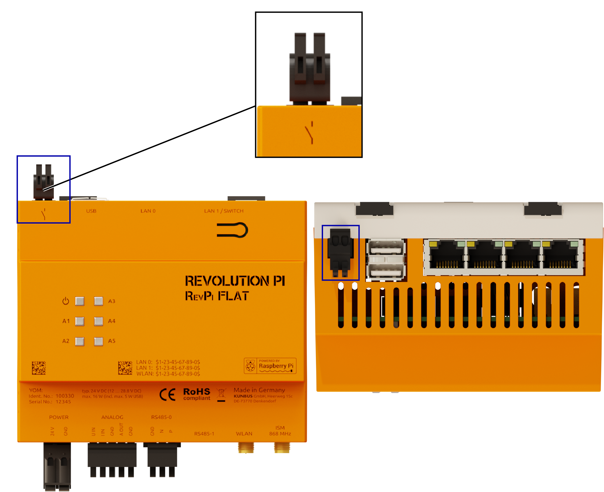
Components #
|
Note
|
The components of the RevPi may vary depending on the variant. |
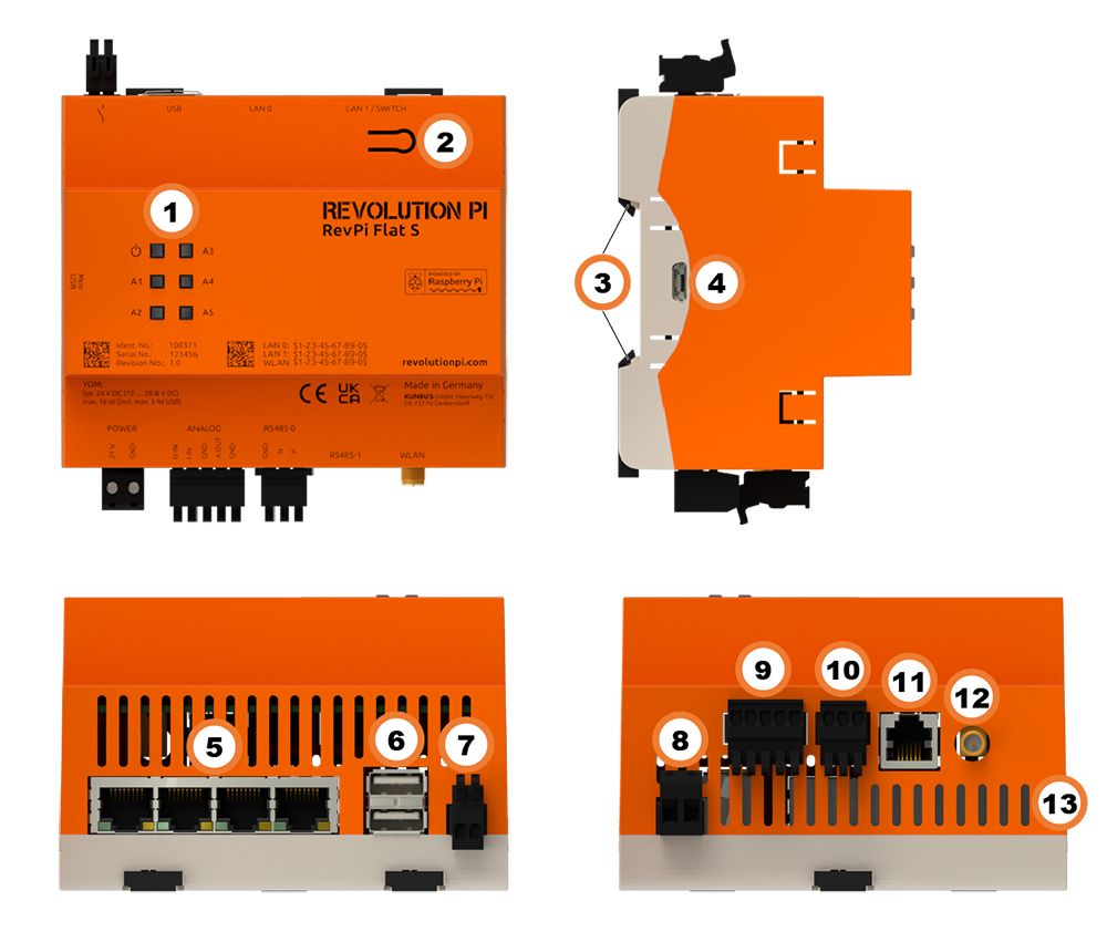
| Position | Component | Application |
|---|---|---|
1 |
6 × status LED |
|
2 |
Button |
|
3 |
2 × locking clip |
|
4 |
Micro-USB[1] |
|
5 |
4 × RJ45 Ethernet |
|
6 |
2× USB A |
|
7 |
Digital output (relay contact) |
|
8 |
POWER |
|
9 |
Analog input / |
|
10 |
RS485-0 |
|
11 |
RS485-1 |
|
12 |
RP-SMA socket |
|
13 |
Ventilation Slots |
Variants #
RevPi Flat S #
| Item No. | RAM | eMMC | Micro-USB |
|---|---|---|---|
100371 |
1 GB |
32 GB |
✔ |
RevPi Flat #
| Item No. | RAM | eMMC | Micro-USB |
|---|---|---|---|
100330 |
1 GB |
8 GB |
- |
|
Note
|
The RevPi Flat was designed as a tamper-proof device. Therefore, it is not intended that you can flash the image of the RevPi Flat (unlike the product model RevPi Flat S). |
For available variants see Revolution Pi Shop.
Compatibility #
Operating System Images #
The RevPi Flat S[microUSB] is compatible with:
-
RevPi Bullseye
|
Note
|
The RevPi Flat was designed as a tamper-proof device. Therefore, it is not intended that you can flash the image of the RevPi Flat (unlike the product model RevPi Flat S). |
Scope of Delivery #
The scope of delivery includes
-
RevPi Flat S or Rev Pi Flat (non-modular base module)
-
2-pin plug POWER
-
5-pin plug ANALOG
-
3-pin plug RS-485-0
-
2-pin plug for relay contact
-
Supplement
Mounting and Connecting #
The RevPi was developed for use in a control cabinet. Observe the specifications for the Intended Use and all Safety Instructions.
|
Warning
|
Danger to life due to electrical shock
There is a risk of fatal electrical shock when working on devices in the switch cabinet with 230 V mains voltage. ▷ Operations in the switch cabinet may only be carried out by qualified electricians. ▷ Before carrying out any operations in the switch cabinet, switch off the power supply properly. |
|
Caution
|
Damage to the device due to overheating
The ambient temperature in the switch cabinet must not exceed the maximum permissible operating temperature. ▷ Keep ventilation slots clear. ▷ Observe the installation clearances. ▷ Mount the device in the intended orientation. ▷ Do not place appliances with high input power directly next to each other. ▷ Regularly remove dust and dirt from the area around the appliance. |
Carry out the installation and connection in the following order:
-
Mount your RevPi on a DIN rail.
-
Connect all other devices such as sensors and actuators. The interfaces available to you for this can be found in the Components section.
-
As the last step connect the power supply.
Connecting the Power Supply #
|
Warning
|
Danger to life due to electrical shock
There is a risk of fatal electrical shock when working on devices in the switch cabinet with 230 V mains voltage. ▷ Operations in the switch cabinet may only be carried out by qualified electricians. ▷ Before carrying out any operations in the switch cabinet, switch off the power supply properly. |
|
Caution
|
Damage to the device due to impermissible power supply
▷ Observe the maximum voltage supply of 28.8 V DC. ▷ Only use the supplied plug and a suitable power supply unit. ▷ Ensure correct polarity when connecting. ▷ Ensure a stable power supply. |
|
Caution
|
Damage to the device due to installation under voltage supply
While the RevPi device is connected to a power source, no other devices may be connected or disconnected, as this may cause damage to the devices. ▷ Do not connect the power supply until all other devices are connected correctly. ▷ Switch off the power supply before disconnecting a device from the system. |
|
Caution
|
Damage to the device software due to disconnection from the power supply
If the device is disconnected from the power supply during operation, the file system of the eMMC memory may be destroyed. The device can then no longer be booted. ▷ Shut down the device properly before disconnecting it from the power supply. |
|
Caution
|
Damage to the device due to different grounding
▷ Refer all connections to the same system ground. ▷ Connect external voltage inputs or outputs with different grounding externally. |
This power supply requires cabling via the POWER plug.
You will need:
✓ A power supply unit (min. 20 W, e.g. DIN rail switching power supply, article no. 200003)
✓ Wiring, cross section 0.35…2.5 mm
✓ Stripping and crimping pliers
✓ If you use stranded wire, apply suitable wire end sleeves
✓ A small slotted screwdriver
▷ Disconnect connected devices from their respective power supply.
▷ Connect the power supply according to the following pin assignment:
| Pin | Function |
|---|---|
24V |
24 V supply, between 10.7 … 27.8 V |
GND |
0 V supply |
Access to the Device #
The RevPi is accessed in two steps:
Install all available updates as soon as the RevPi is connected to the internet. This ensures that the system is always up to date with security-relevant features.
See also:
Configuration #
The RevPi is configured in two steps:
|
Note
|
CODESYS and PiCtory cannot be used in parallel for configuration. An existing configuration via PiCtory will be overwritten by a configuration via CODESYS. The virtual devices OPC UA Server and MQTT Client can only be used via PiCtory. |
Parameterization #
The following parameters, inputs (INP), outputs (OUT) and memory variables (MEM) can be configured:
AIn (INP) #
Displays the input values of the analog inputs.
AIn_Status (INP) #
Displays the status of the analog inputs.
AOut_Status (INP) #
Displays the status of the analog outputs.
Core_Temperature (INP) #
Displays the CPU temperature as an integer value in degrees Celsius (°C).
Core_Frequency (INP) #
Displays the CPU frequency in MHz / 10, e.g. 2400 MHz = value 240.
Top_Button (INP) #
Displays the input value of the push-button.
RevPiLED (OUT) #
The freely programmable LEDs can be controlled via RevPiLED, see Configuring LEDs.
| Bit | Component | Status Information |
|---|---|---|
2:0 |
LED A1 |
000 = off |
AOut (OUT) #
Displays the output value for the analog output.
DOut (OUT) #
Displays the output value for the digital output.
AInMode (MEM) #
Is the mode for the analog input:
-
Voltage 0 - 10V for voltage measurement
-
Current 0 -. 20mA for current measurement
RS485 Serial Interface #
The RevPi has two RS485 interfaces. This allows you to use serial protocols such as Modbus and to integrate devices such as smart meters or solar inverters into your the Revolution Pi system.
The interfaces are labeled with RS485-0 and RS485-1 . Both interfaces are isolated galvanically from each other and from the RevPi.
Under Linux, the interfaces can be addressed with:
-
ttyAMA0( RS485-0) -
ttyS0( RS485-1)
RS485-0
RS485-0 is connected to a 3-pole terminal. The data lines are marked with P (positive) and N (negative). For other devices, these lines are often referred to as D+ and D- or A and B.
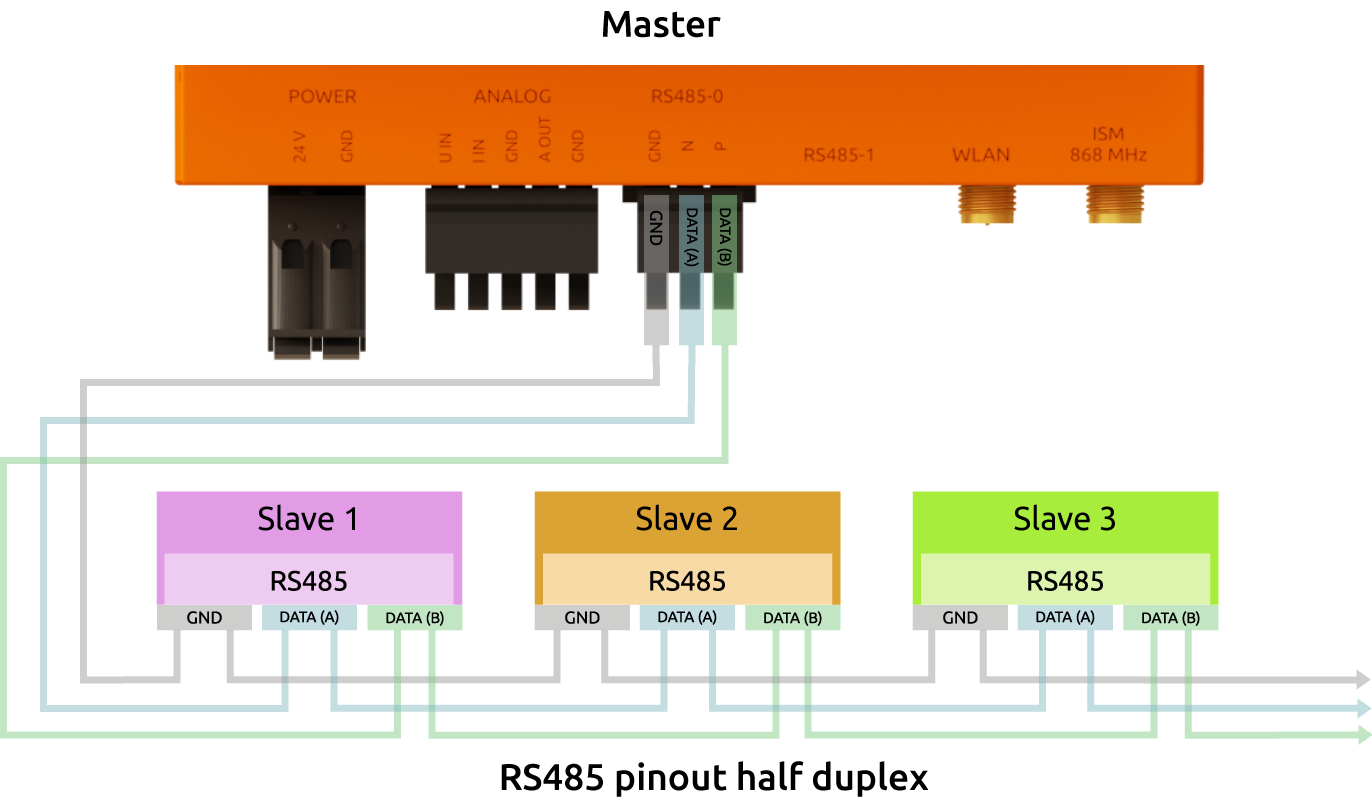
Only the lines N and P are required for the actual data transmission. We recommend a twisted pair for longer line lengths or larger baud rates.

RS485-1
An RJ11 socket is available for RS485-1.
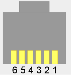
| Pin | Wiring |
|---|---|
1 |
— |
2 |
GND |
3 |
Negative |
4 |
Positive |
5 |
GND |
6 |
— |
Reference Potential
Should a reference potential be necessary, you can use the GND electrical circuit ground of the respective RS485 bus for this purpose. Since the two RS485 systems have complete galvanic isolation from each other and from the rest of the RevPi Flat circuitry, these GND connections are also isolated galvanically from each other and from the RevPi Flat GND connection.
Shielding
Cables having a length over 30 meters and cables leaving the building should be shielded. To further improve the EMC properties of the shield, you can connect the shield to the equipotential bonding rail of the distribution box if necessary. Such a connection can easily be made with a contact force spring.
Bit Rates
Linux addresses the interfaces via the character devices /dev/ttyAMA0 and /dev/ttyS0. You can configure bit rates from 50 to 3,000,000 for /dev/ttyAMA0 and from 1,200 to 4,000,000 for /dev/ttyS0. However, occasional reception errors may occur at more than 230,400 bits. The reason is that the UART of the Raspberry Pi, to which the interface is connected, has only a 16 byte FIFO and does not support DMA. The higher the bit rate, the more often the FIFO is not read out fast enough and received data is lost. For example, there are 1 - 2 errors per 50 MByte received at 460,800 bits and there are about 10 errors at 921,600 bits. If your RevPi Flat mainly sends data and only rarely receives it, you can also use higher bit rates. Otherwise we recommend to not set more than 230,400 baud.
Activating Termination Resistor
✓ The integrated 120 Ω terminating resistor of the RS485 interface is switched off after a restart.
▷ Log in to the RevPi via a terminal.
▷ Check out the Git repository of the command line tool rs485_config from GitLab with the command:
git clone https://gitlab.com/revolutionpi/rs485_config.git▷ Build the tool with the command:
cd rs485_config; make▷ Activate the resistor with the command:
./rs485_config <SERDEV> --set-bus-termReplace <SERDEV> with the name of the interface, e.g. /dev/ttyRS485.
▷ Check whether the resistor has been activated and display the settings of the RS485 interface with the command:
./rs485_config <SERDEV>❯❯ If the resistor is activated, Bus termination: Yes is output.
RJ45 Ethernet Interfaces #
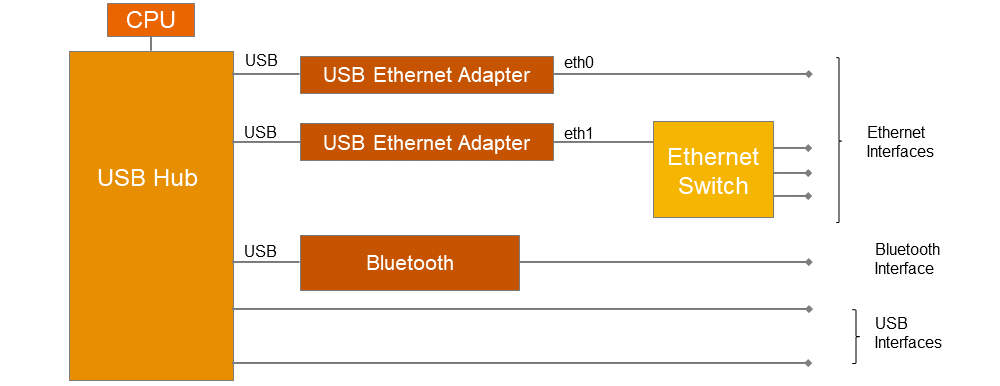
The RevPi has two 10/100 Ethernet interfaces with one or three RJ45 sockets for two or four independent MAC addresses. With active autonegotiation, they support half and full duplex.
A transmission rate of 100 MBit/s is available for each interface. All Ethernet interfaces are connected to the internal USB hub. As USB interfaces and Ethernet interfaces share a USB bandwidth, the transfer rate may be reduced if additional USB devices are connected.
LAN 0
The MAC address for LAN 0 is printed on the front of the housing.
-
As of RevPi Trixie the interface can be addressed under Linux via:
lan0 -
Until RevPi Bookworm the interface can be addressed under Linux via:
eth0
LAN 1 (switch) or LAN 1 … LAN 3
Up to three additional devices can be connected to a network via the three RJ45 sockets for LAN1. They are connected to the internal USB hub via a 1:3 switch. The MAC address for LAN 1 is printed on the front of the housing.
-
As of RevPi Trixie the interface can be addressed under Linux via:
lan1 -
Until RevPi Bookworm the interface can be addressed under Linux via:
eth1
The three connections for LAN 1 can be assigned to independent MAC addresses via DSA. The storage location for the MAC addresses is /boot/config.txt.
If no addresses are entered in this file or after a new image has been installed, the factory MAC addresses are used.
WLAN and BT #
|
Note
|
In accordance with EU regulations, operation in the 5150 … 5350 MHz frequency band is restricted to indoor use. This restriction applies in the Member States of the European Union and in the United Kingdom (Northern Ireland). |
WLAN Interface
✓ RevPi base module with WLAN interface
✓ DHCP-enabled WLAN router
▷ Set up the WLAN connection via NetworkManager.
BT Interface
A BT interface[3] is available from standard 5.0.
▷ Activate BT via Cockpit in order to connect Bluetooth peripheral devices such as keyboards or audio devices to the RevPi.
See also:
USB Interfaces #
The RevPi has two USB-A Interfaces. This allows USB 2.0 client devices such as USB hard disks, surf sticks, keyboards or mice to be connected.
the power consumption of the connected devices must not exceed 2.5 W (500 mA @ 5 V) per port. In the event of an overload, the power is switched off at the corresponding USB interface.
The USB interfaces share a USB hub on the RevPi with the two Ethernet interfaces and a Bluetooth interface. This can influence the maximum bandwidth.
The USB interface is suitable for a maximum of 64 DAM-based USB devices.
You can display the USB devices connected to the USB subsystem with the following:
pi@RevPi0000:~ $ lsusb -t
/:    Bus 01.Port 1: Dev 1, Class=root_hub, Driver=dwc_otg/1p, 480M
|__ Port 1: Dev 2, If 0, Class=Hub, Driver=hub/5p, 480M
|__ Port 1: Dev 3, If 0, Class=Vendor Specific Class, Driver=smsc95xx, 480M`
|__ Port 4: Dev 4, If 0, Class=Vendor Specific Class, Driver=smsc95xx, 480M`
|__ Port 5: Dev 5, If 0, Class=Vendor Specific Class, Driver=ftdi_sio, 12M
Digital output (relay contact) #
You can use the digital output to switch external devices on and off, for example. It is designed as a potential-free relay contact. Control is therefore effected via a mechanical connection of the pins.
The relay contact may be loaded with a maximum of 30 V DC or 24 V AC and 2 A.
A suppressor diode is connected in parallel with the relay contact to reduce the switching arcs that occur when switching inductive loads. This reduces wear. An external free-wheeling diode or equivalent protective circuitry is not required.
Controlling with piTest
You can switch the relay via piTest with the -w option:
▷ Activate the relay with the command
piTest -w DOut,1▷ Deactivate the relay with the command
piTest -W DOut,0Direct Control
You can use the gpio program for direct control of the relay via operating system functions. First you must switch the corresponding GPIO - pin — in this case pin 28 — as the output. Then you can set the output with 1 for switch on and 0 for switch off. The example below shows the corresponding sequence of commands:
▷ Set the pin as the output with the command
gpio mode 28 out▷ Switch the output on with the command
gpio write 28 1▷ Switch the output off with the command
gpio write 28 0Analog Inputs and Outputs #
The RevPi has one analog input and one analog output on the 5-pin ANALOG connector.
Analog input
The analog input can be used to measure either voltage or current.
-
U IN: Voltage measurement 0 … 10 V DC
-
I IN: Current measurement 0 … 20 mA DC
Current and voltage input must not be connected at the same time, otherwise the measurement result will be distorted.
The current is converted into a proportional voltage via an internal 240 ohm resistor.
The MCP3550-50 analog-to-digital converter (ADC) used for this purpose offers a high usable resolution of 21 bits, but at 85 milliseconds per measurement, it requires a comparatively long time.
There are two ways to access the interfaces: either by reading and writing the Linux sysfs or by using our RevPi configuration tool PiCtory and the software tool piTest, which allows you to access the process image of the system. In the following we describe both methods separately for input and output.
Reading out Values with Linux sysfs
Read out voltage 0 … 10 V:
▷ Obtain the input value of the ADC with:
cat /sys/bus/iio/devices/*/in_voltage0*▷ Convert the raw value read out to in_voltage0-voltage1_raw with the formula ($raw * 12500) >> 20) + 12500 to obtain the voltage in mV.
Read out current 0 … 20 mA:
✓ The current should be on the port I IN: are available.
▷ Divide the read out voltage (see above) by a resistance of 240 ohms to obtain the current in mA.
Reading out Values with piTest
You can configure the current/voltage mode for the RevPi Flat in PiCtory with the variables AInMode :
-
AInMode Voltage 0-10V (standard)
-
AInMode Current 0- -20mA
▷ Simply read out the current or voltage value by entering
piTest -r AInAnalog output
You can connect actuators such as frequency converters to the analog output. It can output a voltage between 0 and 10 V.
The DAC121S101 digital-to-analog converter (DAC) used for this purpose has a resolution of 12 bits.
Entering Values with Linux sysfs
▷ Enter the value in the DAC with:
echo 2047 | sudo tee /sys/bus/iio/devices/*/out_voltage0_raw▷ Enter a value between 0 and 4095 into the DAC out_voltage0_raw to output a voltage between 0 and 10 V.
Entering Values with piTest
▷ Enter the analog value in mV in the variable AOut e.g. 5000 mV for the analog output:
piTest -w AOut,5000More information on implementation
On the software side, the DAC121S101 and MCP3550-50 are treated like I/O modules whose interface is implemented in sysf as /sys/bus/iio/devices/.
After the converters are successfully registered, the following kernel log usually appears.
pi@RevPi0000:~ $ dmesg | grep "spi.*consumer
[ 4.461004] mcp320x spi0.1: Linked as a consumer to regulator.1
[ 5.747592] ad5446 spi0.0: Linked as a consumer to regulator.2
Two subfolders are added to the folder sysfs for the converters as /sys/bus/iio/devices/iio:deviceX. You can use × to distinguish between the converters here. The order depends on the registration of the devices and therefore has no fixed assignment. The assignment becomes apparent, however, when you look at the contents of the folders. The folder with the files out_voltage is the output module and therefore the DAC module. The folder with the files in_voltage is the input module and therefore the ADC module.
In the method with piTest, piControl retains these values permanently in the process image and you can read and write the values with piTest.
See also:
Date and Time #
Different mechanisms are used for time management in the RevPi. They serve different purposes and complement each other.
Network Time Protocol (NTP)
Network Time Protocol (NTP) automatically synchronizes the system time of the RevPi with a time server.
Real-Time Clock (RTC)
The RevPi is equipped with a real-time clock. When no supply voltage is present at the RevPi, the RTC is powered by a supercapacitor.
The supercapacitor is charged during operation and typically maintains the time for up to 24 hours. The actual duration depends on the environmental conditions.
See also: Real-Time Clock (RTC) in RevPi Devices.
Trusted Platform Module (TPM) #
The RevPi is equipped with the Trusted Platform Module Infineon OPTIGA™ TPM SLB 9670. It fulfills the requirements of TPM 2.0.
Under Linux you can address the module with /dev/tpm0.
Watchdog #
The RevPi has two independent watchdogs. The first is part of the BCM2837 SoC, which is also used on the Raspberry Pi 3. The second is the Maxim MAX6370 external watchdog module.
BCM2837
The BCM2837 watchdog is the preferred watchdog because it behaves like other watchdogs under Linux. You can access it either via the device file /dev/watchdog0 or as a default watchdog via the device file /dev/watchdog.
MAX6370
The MAX6370 can be accessed via the device file /dev/watchdog1.
To activate it, GPIO4 must be set high once. It can no longer be deactivated via this GPIO, however. For activation via the command line, you can use the gpiod tool:
gpioset -m time -u 1000 pinctrl-bcm2835 4=1gpiod Package
The command gpioset is part of the gpiod package. If this is not installed, you can install it yourself with:
sudo apt install gpiodIf you want to operate the GPIO from your application, the libgpiod is right for you. This also provides a Python interface.
You will need the following packages:
-
libgpiod‑dev -
libgpiod2 -
python3‑libgpiod
The timeout of the MAX6370 is fixed at 60 seconds and cannot be changed.
Once activated, the Watchdogs MAX6370 can only be deactivated by disconnecting the power supply. A restart does not deactivate the watchdog. This means that a restart must not take longer than 60 seconds when the watchdog is active, otherwise the hardware will be reset.
Watchdog under Linux
There are several ways to use a watchdog under Linux. Revolution Pi and Raspbian Pi rely on systemd. This is therefore also the preferred method of using the watchdog. systemd can be used to trigger a hardware watchdog. Applications that are to be monitored by the watchdog are then monitored by systemd. This has the advantage that several applications can be monitored. Consequently, the entire system does not necessarily have to be restarted, but instead only the individual application.
See also:
Freely configurable push-button #
The RevPi has a freely configurable button. The input value of the button can be evaluated via GPIO13 and then used for certain actions, e.g. for a controlled shutdown of the RevPi.
In the PiCtory Value Editor, the input value of the push-button is entered under Top_Button displayed.
It can be retrieved by software in the same way as a keyboard entry. The KEY_UNKNOWN key code is used (corresponds to value 240).
Technical Data #
Item No.: 100371
Housing dimensions (H × W × D) |
90 × 106 × 70 mm |
Housing type |
DIN rail housing for TH35 mounting rail according to DIN EN 60715 |
Housing material |
Polycarbonate |
Weight |
Approx. 256 g (incl. connectors) |
Protection class |
IP20 / NEMA Class 1 |
Power supply |
Typ. 24 V DC (12,0 … 28,8 V DC), reverse-polarity protected |
Maximum power consumption |
11 W (incl. 5 W USB) |
Approved operating temperature |
-20 … +55 °C |
Approved storage temperature |
-40 … +85 °C |
Max. relative humidity (at 40 °C) |
93 % (non-condensing) |
Interfaces |
|
Connectors |
2-, 3- and 5-pole screw/spring-loaded terminal |
Compute Module |
Raspberry Pi Compute Module 4S |
Processor |
Broadcom BCM2711, quad-core Arm Cortex-A72 |
Clock rate |
1.5 GHz |
Processor cooling |
Passive with heat sink |
RAM |
1 GB LPDDR4 |
Flash memory |
32 GB |
Trusted Platform Module |
TPM 2.0 Infineon OPTIGA™ TPM SLB 9670 |
WLAN / BT |
|
Number of digital outputs |
1 |
Output type |
Potential-free relay contact (NO) |
Maximum current output channel |
2 A @ 30 V DC |
Number of analog inputs |
1 |
Analog input type |
0 … 10 V DC or 0 … 20 mA, single-ended, 16 bit at piControl, 21 bit raw value |
Number of analog outputs |
1 |
Analog output type |
0 … 10 V DC, short-circuit proof, protection against backfeeding (max. +Ub = 28,8 V), 12 bit resolution, gain error 3 % of measured value, offset error +/-50 mV |
Maximum current load of the analog output |
10 mA (10 V DC @ 1k) |
Software connection of inputs and outputs |
Via GPIOs and process image |
EMC interference emission |
According to EN 61000-6-4 |
EMC immunity |
According to EN 61000-6-2 |
Buffer time RTC |
Min. 24 h |
Optical display |
6 status LEDs (bi-color), 5 of them freely programmable |
Conformity |
CE, RoHS, UKCA |