Product Description #
The RevPi Con CAN is an expansion module for RevPi Connect for connection to the CAN bus.
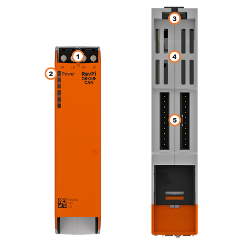
Components #
| Position | Component | Application |
|---|---|---|
1 |
X2 connector |
|
2 |
Status LED |
|
3 |
Locking clamps |
|
4 |
Ventilation Slots |
|
5 |
2× ConBridge |
LED #
Power #
The Power LED indicates the device status.
| Signal | Function |
|---|---|
Green |
Power supply is connected. |
Red |
There is a fault. |
Compatible Base Modules #
-
RevPi Connect SE
-
RevPi Connect+
-
RevPi Connect S
The RevPi Con modules can each be connected to the right-hand side of the base module via the ConBridge.
Mounting and Connecting #
The RevPi was developed for use in a control cabinet. Observe the specifications for the Intended Use and all Safety Instructions.
Connecting RevPi Con Modules #
|
Important
|
Damage to the device due to installation under voltage supply
While the RevPi device is connected to a power source, no other devices may be connected or disconnected, as this may cause damage to the devices. ▷ Do not connect the power supply until all other devices are connected correctly. ▷ Switch off the power supply before disconnecting a device from the system. |
|
Important
|
Damage to the devices due to mix-up of the plug connectors
▷ Only connect RevPi I/O modules and RevPi gateways to the system via the black PiBridge plug connectors. ▷ Only connect RevPi Con M-Bus and RevPi Con CAN to the system via the gray ConBridge plug connectors. |
The RevPi Con modules are connected to a RevPi Connect base module via gray ConBridge plug connectors and supplied with power. A plug connector is included in the scope of delivery of a RevPi Con module or can be ordered via the store (article no. 100297).
RevPi Con modules can only be connected on the right-hand side of the following base modules.
| Left side | base module | Right side |
|---|---|---|
5 × RevPi I/O module |
RevPi Connect SE |
1 × RevPi Con CAN, |
5 × RevPi I/O module, including 1 × RevPi Gateway |
RevPi Connect+RevPi Connect S |
1 × RevPi Con CAN, |
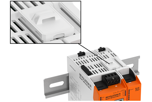
▷ Mount your RevPi base module on the DIN rail.
▷ Mount the RevPi Con module to the right of the RevPi base module on the DIN rail.
▷ Connect the RevPi devices with the gray ConBridge plug connector on the top of the housing.
Connecting RevPi Con CAN to the CAN Bus #
You can connect the RevPi Con CAN to the CAN bus using the X2 connector.
| Pin | Function |
|---|---|
1 |
Resistance 60 Ω |
2 |
CAN_L |
3 |
CAN_H |
4 |
Resistance 60 Ω |
Avoid reflections #
Reflections can interfere with your data communication. They can occur anywhere where there is a physical irregularity, e.g.
-
At the end of a line
-
At the transition of a line
-
On a damaged cable
If your signal encounters such an irregularity, part of the signal is reflected and it moves in both directions on the transmission line. The same signal thus reaches the same receiver twice.
However, you can avoid reflections by making a few simple preparations:
▷ Activate the terminating resistor for devices located at the beginning and end of the line.
▷ With your RevPi Con CAN, you must connect pins 1 and 2 and pins 3 and 4 with a wire bridge.
▷ Check whether your cables are damaged.
▷ Make sure that your cables are laid straight.