Objective: Use a RevPi base module as a Modbus RTU Client to read data from or write data to server devices. The configuration is performed in the RevPi application PiCtory.
Using the RevPi as a Modbus RTU Client is suitable for scenarios where devices such as sensors, actuators, or other industrial devices need to be controlled or monitored via a serial RS485 connection.
This tutorial applies to RevPi base modules that either have an integrated RS485 interface or are connected via a USB-RS485 adapter.
Prerequisites #
Devices
✓ Modbus Server device(s)
✓ Option: USB-RS485 adapter
Hardware Installation
✓ The RevPi base module is connected to the network.
✓ The RevPi base module is connected to the power supply.
✓ The server devices are connected to the RevPi via the RS485 interface or a USB-RS485 adapter.
See also:
-
RevPi Connect 5: RS485 Serial Interface
-
RevPi Connect 4: RS485 Serial Interface
-
RevPi Connect S/SE: RS485 Serial Interface
-
RevPi Flat S: RS485 Serial Interface
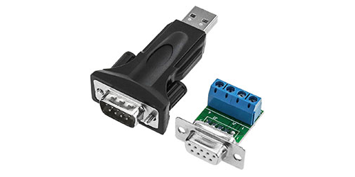
Connecting a USB-RS485 Adapter:
▷ Connect a USB-RS485 adapter to the USB port of the RevPi.
▷ Connect a D-Sub 9 connector to the adapter to connect it to the server devices.
| Signal | D-Sub Pin |
|---|---|
RS485- |
1 |
RS485+ |
2 |
GND |
5 |
+5V |
6 |
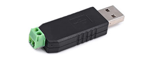
With some USB-to-RS485 adapters, only the RS485 data signal lines (D+ and D-) are connected.
Software Installation
✓ Web browser (e.g., Chrome, Firefox, or Edge)
✓ The RevPi and the server devices are on the same network.
✓ Each server device has a unique address.
✓ The address, baud rate, parity, data bits, and stop bits of all server devices are documented according to the manufacturer’s specifications.
|
Note
|
Multiple server devices should not have the same address on the same RS485 bus, as this causes communication errors. |
|
Note
|
As of RevPi Bookworm (08/2025) the firewall on the RevPi must also be enabled to allow the default ports of the Modbus server: ▷ Add the service revpi-modbus-default to the firewall settings in Cockpit, see Firewall. |
1. Configuring the Modbus RTU Client in PiCtory #
▷ Start PiCtory.
▷ Drag the RevPi base module from the Device Catalog to the empty slot in the configuration area with position number 0.
▷ Drag a Modbus RTU Client from Virtual Modbus Devices in the Device Catalog to the base module in the configuration area.
▷ Optional: Add multiple Modbus RTU Clients to expand the capacity for additional values.
❯ The Modbus RTU Client is now displayed in the configuration area.
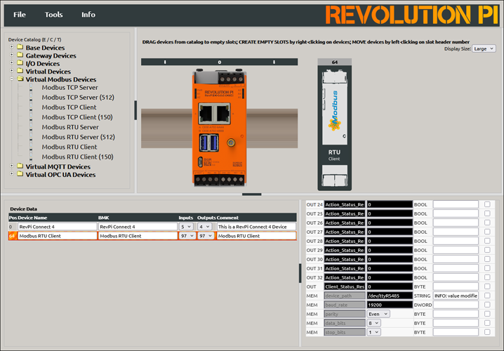
▷ Select the Modbus RTU Client in the configuration area.
▷ Configure the following parameters at the very bottom of the list in the Value Editor:
| Parameter | Description |
|---|---|
Input_ |
Up to 32 input values, each 16 bits wide. |
Output_ |
Up to 32 output values, each 16 bits wide. |
device_path |
Path to the Linux device file. |
baud_rate |
Speed of the serial connection. |
parity |
Parity bit configuration: |
data_bits |
Number of data bits. |
stop_bits |
Number of stop bits. |
|
Note
|
Configure |
▷ In the Value Editor, you can assign suitable I/O names for easier reference, e.g., Modbus_Input_1.
See also Configuring Values.
▷ Select to save the configuration.
▷ Select to apply the configuration.
2. Configuring Modbus Commands #
▷ Open the context menu of the Modbus RTU Client in the configuration area.
▷ Select Extended Data to open the command configuration window.
▷ Configure the commands using the following parameters:
| Parameter | Description |
|---|---|
Slave Addr. |
This address can be found in the server manual. |
Function Code |
|
Register Addr. |
Define the Modbus register or bit address to be accessed. |
Quantity of Registers |
Number of registers or bits to read/write. |
Action Interval (ms) |
Time interval for sending the command in milliseconds. |
Device Value |
Name of the variable in the process image. |

|
Note
|
For devices that use 0-based addressing, the register address must be incremented by 1 during configuration. |
▷ Select to save the configuration.
▷ Select to apply the configuration.
Error Codes #
▷ If communication problems occur, check the Modbus_Client_Status register in the Value Editor.
▷ To reset an error, manually write 1 to the Client_Status_Reset or Action_Status_Reset register.
Common error codes:
| Code | Description |
|---|---|
|
The serial device could not be opened or found. Check |
|
No valid response received from the Modbus server. |
|
ILLEGAL FUNCTION: Invalid function code. |
|
ILLEGAL DATA ADDRESS: Invalid or write-protected register address. |
|
INVALID CRC: Corrupted packet. Check wiring, connection, and serial parameters. |
|
Connection timeout. |
Possible error causes:
-
RS485 connection interrupted or A/B lines swapped
-
Incorrect path in
device_path_ -
Incorrect server address, baud rate, parity, data bits, or stop bits
-
Invalid register address
-
Overlapping or conflicting Modbus commands
-
Action interval too short under high bus or system load