Product Description #
The RevPi Connect 5 is a 24 V industrial PC for IIoT and automation projects based on the Raspberry Pi Compute Module 5. The RevPi is a base module from the Revolution Pi product family. All devices in the Revolution Pi family are developed in accordance with EN 61131-2.
Components #
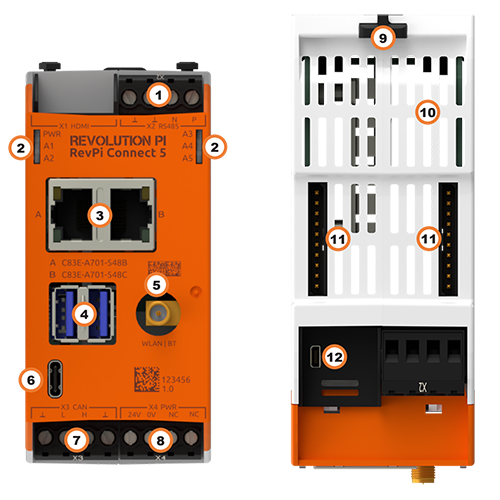
| Position | Component | Application |
|---|---|---|
1 |
X2 RS485[1] |
|
X2 CAN[1] |
||
2 |
6 × status LED |
|
3 |
2 × RJ45 Ethernet |
|
4 |
2 × USB A 3.2 Gen 1 |
|
5 |
RP-SMA[1] |
|
6 |
USB-C |
|
7 |
X3 CAN[1] |
|
8 |
X4 PWR |
|
9 |
2 × locking clip |
|
10 |
Ventilation Slots |
|
11 |
2 × PiBridge |
|
12 |
X1 HDMI |
Compatible RevPi Image
-
RevPi Bookworm Image
See RevPi Images.
Variants #
| Item no: | RAM | eMMC Memory | WLAN BT | RS485 | CAN |
|---|---|---|---|---|---|
100412 |
4 GB |
32 GB |
- |
× |
- |
100413 |
4 GB |
32 GB |
× |
× |
- |
100414 |
4 GB |
32 GB |
- |
× |
1 × |
100415 |
4 GB |
32 GB |
× |
× |
1 × |
100416 |
8 GB |
32 GB |
- |
× |
- |
100417 |
8 GB |
32 GB |
× |
× |
- |
100418 |
8 GB |
32 GB |
- |
× |
1 × |
100419 |
8 GB |
32 GB |
× |
× |
1 × |
100420 |
8 GB |
32 GB |
× |
- |
2 × |
For available variants see Revolution Pi Shop.
Expansion Modules #
The RevPi Connect 5 base module can be expanded by up to 10 expansion modules to create a Revolution Pi system:
| Left side | Base module | Right side |
|---|---|---|
5 × RevPi I/O module, including 1 × RevPi Gateway |
RevPi Connect 5 |
5 × RevPi I/O module, including 1 × RevPi Gateway |
Compatible RevPi I/O Modules #
Compatible RevPi Gateways #
RevPi Gateways can only be connected to the far right or far left of the system via a PiBridge plug connector.
-
RevPi Gate PROFINET
-
RevPi Gate EtherNet/IP
-
RevPi Gate EtherCAT
-
RevPi Gate PROFIBUS
See RevPi Gateways
Mounting and Connecting #
The RevPi was developed for use in a control cabinet. Observe the specifications for Intended Use and all Safety Instructions.
|
Warning
|
Danger to life due to electrical shock
There is a risk of fatal electrical shock when working on devices in the switch cabinet with 230 V mains voltage. ▷ Operations in the switch cabinet may only be carried out by qualified electricians. ▷ Before carrying out any operations in the switch cabinet, switch off the power supply properly. |
Carry out mounting and connection in the following order:
-
Mount the RevPi base module and all expansion modules on a DIN rail.
-
Connect all expansion modules via PiBridge plug connector.
-
Connect all other devices such as sensors and actuators. The interfaces available to you for this can be found in the section Components.
-
Connect a monitor and a keyboard if you want to operate the RevPi in the desktop mode. This is not necessary if you have a network connection to access the RevPi.
-
Finally, connect the power supply.
Access to the Device #
The RevPi is accessed in two steps:
Install all available Updates as soon as the RevPi is connected to the internet, so that the system is always up to date with security-relevant features.
Alternatively, access is possible without a network, see Desktop Mode.
See also:
Configuration #
The RevPi is configured in two steps:
-
From the RevPi Bookworm Image (10/2024) onwards, the basic configuration of the RevPi devices is carried out via the Cockpit web application:
-
Network configuration, user administration, status and log views can be managed via a browser.
-
In addition to the standard server configuration, the Revolution Pi and Node-RED plugins are also available. These allow you to configure your RevPi base module and easily activate or deactivate the installed services.
-
-
The module configuration of a Revolution Pi system, i.e. a RevPi base module with expansion modules, is carried out via the PiCtory application or, if necessary, directly in the development environment, e.g. via CODESYS.
|
Note
|
CODESYS and PiCtory cannot be used in parallel for configuration. An existing configuration via PiCtory will be overwritten by a configuration via CODESYS. The virtual devices OPC UA Server and MQTT Client can only be used via PiCtory. |
Parameterization #
The following parameters, inputs (INP) and outputs (OUT) can be configured:
RevPiStatus (INP) #
Uses bits to represent different states of the piControl driver.
| Bit | Function |
|---|---|
0 |
piControl driver is running. |
1 |
At least one connected I/O module has not been configured. |
2 |
At least one I/O module has been configured but not connected. The bit is also set if a RevPi Gateway has been configured. |
3 |
An I/O module occupies more or fewer bytes in the process image than specified in the configuration. |
4 |
A RevPi Gateway is connected to the left side of the RevPi. |
5 |
A RevPi Gateway is connected to the right side of the RevPi. |
6 |
The limit value of the first error counter RS485ErrorLimit1 has been reached. |
RevPiIOCycle (INP) #
Displays the cycle time of the piBridge communication between the base module and expansion modules in milliseconds (ms) as an integer value.
RS485ErrorCnt (INP) #
Counts the errors in the communication with the RevPi I/O modules and outputs their number as an integer value.
Core_Temperature (INP) #
Displays the CPU temperature as an integer value in degrees Celsius (°C).
Core_Frequency (INP) #
Displays the CPU frequency in MHz / 10, e.g. 2400 MHz = value 240.
RS485ErrorLimit1 (OUT) and RS485ErrorLimit2 (OUT) #
RS485ErrorLimit1 and RS485ErrorLimit2 serve as threshold values for error handling in the communication between the RevPi device and the I/O modules.
At the end of each communication cycle, the error counter [RS485ErrorCnt] is compared with these two limit values:
-
RS485ErrorLimit1: When this value is reached, a message is generated in the log file kern.log. In future piControl versions, the default values defined in PiCtory will also be written to the process image.
-
RS485ErrorLimit2: If the error counter reaches this value, piBridge communication is terminated completely.
|
Note
|
The communication via the serial interface RS485 to the outside is not affected, only the internal piBridge data traffic. |
The respective check is deactivated by setting the corresponding value to 0. If, for example, RS485ErrorLimit1 is set to 0, no warning messages are generated in kern.log.
The default values are:
-
RS485ErrorLimit1: 10
-
RS485ErrorLimit2: 1000
These values offer a good balance between fault tolerance and system stability for most applications.
RevPiLED (OUT) #
The freely programmable LEDs can be controlled via RevPiLED, see Configuring LEDs.
| Bit | Component | Status information |
|---|---|---|
2:0 |
LED A1 |
000 = off |
RS485 Serial Interface #
Serial devices such as sensors can be connected to the RevPi via the potential-free RS485 interface on the X2 connector. The socket has differential data line terminals for P (positive) and N (negative), which may also be designated D/D- or A/B.
The RS485 interface is not available for the product variant with X2 CAN, see variants.
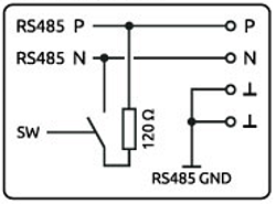
RS485 Connection via X2 Connector
▷ Make sure that all devices are disconnected from their respective power supplies.
▷ Connect the positive data line to pin P of the X2 connector.
▷ Connect the negative data line to pin N of the X2 connector.
▷ Connect the ⫠ pins to the RS485 ground.
▷ Connect the power supply.
Configuring the RS485 Interface
Under Linux, the interface can be addressed via the device driver node with :
-
/dev/ttyRS485-0 -
to RevPi Bullseye Image (4/2024):
/dev/ttyRS485
▷ Log in to the RevPi via a terminal.
▷ Use ls /dev/ttyRS485-0 to check whether the RS485 interface is available.
Activating Termination Resistor
✓ The integrated 120 Ω terminating resistor of the RS485 interface is switched off after a restart.
▷ Check out the Git repository of the command line tool rs485_config from GitLab with the command:
git clone git@gitlab.com:revolutionpi/rs485_config.git▷ Build the tool with the command:
cd rs485_config; make▷ Activate the resistor with the command:
./rs485_config <SERDEV> --set-bus-termReplace <SERDEV> with the name of the interface, e.g. /dev/ttyRS485.
▷ Check whether the resistor has been activated and display the settings of the RS485 interface with the command:
./rs485_config <SERDEV>❯❯ If the resistor is activated, Bus termination: Yes is output.
See also:
CAN Interfaces #
Depending on the Variant, the RevPi has potential-free CAN interfaces on the X3 or X2 connector. The CAN FD Controller MCP251863 is used as the CAN transceiver.

CAN Connection via X3 or X2 Connector
▷ Make sure that all devices are disconnected from their respective power supplies.
▷ Connect the CAN H bus to pin H (High) of the connector.
▷ Connect the CAN L bus to pin L (Low) of the connector.
▷ Connect the ⫠ pins to the CAN ground.
▷ Connect the power supply.
Configuring CAN Interfaces
Under Linux, the interfaces can be addressed with:
-
X3 CAN:
can0 -
X2 CAN:
can1
▷ Log in to the RevPi via a Terminal.
▷ Enter the following command to query the status of the interfaces:
ip link show▷ For example, activate can0 and set the bit rate to 500,000 baud (500 kbit/s) with the command:
sudo ip link set can0 up type can bitrate 500000▷ Activate the 120 ohm termination with the command:
sudo ip link set dev can0 type can termination 120These two possible operating modes are supported:
| Mixed CAN 2.0B and FD mode CAN mode | CAN 2.0B mode |
|---|---|
Simultaneous operation of classic CAN messages (CAN 2.0B) and CAN FD messages (Flexible Data Rate) on the same bus |
Communication exclusively via classic CAN protocol (CAN 2.0B) |
User data of up to 64 bytes and higher bit rates for the data part (up to approx. 8 Mbit/s) |
Messages only with 11-bit or 29-bit IDs. Data rates and user data lengths limited to CAN 2.0B |
Compatible for networks with mixed requirements |
Greater interoperability and stability with older control units |
Ethernet Interfaces RJ45 #
The RevPi can be connected to a network via the RJ45 interface.
Two Gbit Ethernet connections are available on the RevPi, which are independent of each other. This allows the RevPi to be integrated into two different networks. The MAC addresses are printed on the front of the housing. Under Linux, the interfaces can be addressed via:
-
Socket A:
eth0 -
Socket B:
eth1
WLAN and BT #
Prerequisites
-
RevPi base module with WLAN interface
-
DHCP-capable WLAN router
-
Optional: external RP-SMA WLAN antenna
Under Linux, the WLAN interface can be addressed with wlan0 , provided no other WLAN devices are used.
Activate WLAN via Cockpit
See Cockpit.
Set up WLAN Connection via nmtui
The WLAN connection is set up via the NetworkManager nmtui. The NetworkManager is a terminal-based user interface for managing network connections under Linux. It can be started directly via the integrated terminal in Cockpit.
▷ Start Cockpit.
▷ Click on Terminal in the menu to open the integrated terminal.
▷ Start nmtui with the command
sudo nmtui❯ The nmtui user interface appears.
Use the arrow and ENTER buttons to navigate within nmtui.
▷ Select Edit a connection.
▷ Select the appropriate Wi-Fi network (Wi-Fi).
▷ Enter the WLAN password at Password and configure other WLAN settings if necessary.
▷ Save the settings with OK and return to the home screen with Back.
▷ Select Activate a connection.
▷ Select the WLAN network (Wi-Fi) and activate the connection with the ENTER button.
❯ The status message Connecting … appears.
❯ The WLAN connection is established.
▷ Click on _Networking_in the Cockpit menu to check the connection.
BT Interface
A BT interface of standard 5.0 is also available via the same SMA socket as for the WLAN interface.
See Cockpit.
See also:
USB Interfaces #
The RevPi has two USB 3.2 Gen 1 interfaces. The maximum output current per USB interface is 900 mA and is only guaranteed if the RevPi is supplied with 24 V DC -15 % / 20 %.
In the event of an overload, the power is switched off at the corresponding USB interface.
Date and Time / Real Time Clock (RTC) #
The RevPi is equipped with the Real Time Clock NPX PCF2131. If no power supply is connected to the RevPi, the RTC is supplied with power via a backup battery. The lithium battery has a service life of approx. 10 years.
The system time and the RTC are synchronized with an NTP server via the systemd-timesyncd service. Synchronization can be deactivated in Cockpit, for example, in which case the system time is set by the RTC.
Configuring System Time
The command line tool timedatectl can be used to query and change the current system time, the RTC and the configured time zone.
▷ Log in to the RevPi via a terminal.
▷ Check the current settings with the command:
sudo timedatectl status▷ Set the RTC to the coordinated universal time UTC with the command:
sudo timedatectl set-local-rtc 0▷ Set the RTC to a local time zone (e.g. UTC01:00) with the command:
sudo timedatectl set-local-rtc 1▷ To configure your own system time, deactivate NTP synchronization with the command:
timedatectl set-ntp false▷ Then redefine the system time with the command:
timedatectl set-time "YYYY-MM-DD HH:MM:SS"Configuring RTC without NTP Synchronization
The RTC can be set directly using the command line tool hwclock . NTP synchronization must be deactivated for this, as otherwise a synchronized system time will overwrite the set RTC again.
▷ Log in to the RevPi via a terminal.
▷ Deactivate NTP synchronization with the command:
timedatectl set-ntp falseAlternatively, you can deactivate synchronization in Cockpit via the setting Set clock from NTP server .
▷ Check the current settings with the command:
sudo hwclock▷ Synchronize the system time with the RTC using the command:
sudo hwclock --systohc▷ Set the RTC to its own time with the command:
sudo hwclock --set --date "dd mmm yyyy HH:MM"Changing Battery
The lithium battery cannot be replaced by the customer. In this case, please contact customer service at support@kunbus.com.
Trusted Platform Module (TPM) #
The RevPi is equipped with an Infineon OPTIGA™ TPM SLB 9670 Trusted Platform Module. It fulfills the requirements of TPM 2.0.
Under Linux you can address the module with /dev/tpm0.
Watchdog #
A watchdog is a timer that restarts the RevPi after 60 seconds. To prevent this from happening, the watchdog must be reset regularly as long as the system is running without errors. In the event of an error, such as a crash of the application process, there is no reset and the watchdog triggers a restart of the RevPi.
The RevPi has two independent watchdogs. There are various ways to use a watchdog under Linux. The RevPi Images and Raspbian Pi use the system manager systemd.
Integrated Watchdog
The watchdog integrated on the processor behaves like other watchdogs under Linux and can be addressed with:
-
/dev/watchdog0 -
/dev/watchdog(as standard watchdog)
External Watchdog
A second watchdog is available via the RTC module and can be addressed under Linux with:
-
/dev/watchdog1
See also: