Product Description #
The RevPi MIO is an expansion module of the Revolution Pi product family and has 8 analog inputs, 8 analog outputs and 4 digital channels, which can be configured as digital inputs or digital outputs via software.
Components #
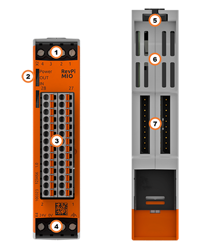
| Position | Component | Application |
|---|---|---|
1 |
X2 connector |
|
2 |
3 × status LED |
|
3 |
8 × analog input |
|
4 |
X4 connector |
|
5 |
Locking clamps |
|
6 |
Ventilation Slots |
|
7 |
2 × PiBridge |
Pinout #
The RevPi MIO has
-
4 digital I/O channels, identically assigned and configurable collectively as either inputs or outputs
-
8 analog inputs for voltage
-
8 analog outputs for voltage
The pins on the connector for the analog inputs and outputs are assigned as follows:
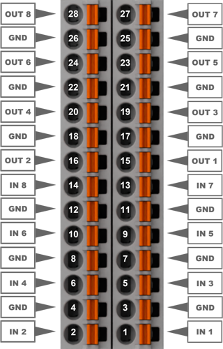
|
Caution
|
Damage to the device due to voltage input on the analog outputs
▷ Make sure the pins are connected correctly. |
For details on configuration, see Parameterization.
LEDs #
The LEDs indicate different device statuses.
Power
| Signal | Function |
|---|---|
Green |
The connection to the RevPi base module is established. |
Flashes red |
The connection to the RevPi base module is being established (initialization phase). |
Red |
The connection to the RevPi base module is interrupted. |
OUT
| Signal | Function |
|---|---|
Flashes red |
A voltage above 10.5 V is set at one or more analog outputs. |
IN
| Signal | Function |
|---|---|
Green |
One or more analog inputs are being used. |
Flashes red |
The voltage at one of the inputs exceeds the defined value of 10 V. |
Compatible Base Modules #
-
RevPi Core (all variants)
Left side only:
-
RevPi Connect+
-
RevPi Connect
See also Rules for the Arrangement of Devices.
Scope of Delivery #
The scope of delivery includes
-
RevPi MIO (expansion module)
-
PiBridge plug connector
-
X2 connector
-
X4 connector
-
2 × 14-pin I/O connector
-
Product insert
Mounting and Connecting #
The RevPi was developed for use in a control cabinet. Follow the specifications for Intended Use and all Safety Instructions.
|
Warning
|
Danger to life due to electrical shock
There is a risk of fatal electrical shock when working on devices in the switch cabinet with 230 V mains voltage. ▷ Operations in the switch cabinet may only be carried out by qualified electricians. ▷ Before carrying out any operations in the switch cabinet, switch off the power supply properly. |
|
Caution
|
Damage to the device due to overheating
The ambient temperature in the switch cabinet must not exceed the maximum permissible operating temperature. ▷ Keep ventilation slots clear. ▷ Observe the installation clearances. ▷ Mount the device in the intended orientation. ▷ Do not place appliances with high input power directly next to each other. ▷ Regularly remove dust and dirt from the area around the appliance. |
Carry out the mounting and connection in the following order:
-
Mount the RevPi base module and all expansion modules on a DIN rail.
-
Connect the expansion module via PiBridge plug connector.
-
Connect all other devices such as sensors and actuators.
-
Finally, connect the power supply.
Connecting the System Ground (GND) #
|
Caution
|
Damage to the device due to different grounding
▷ Refer all connections to the same system ground. ▷ Connect external voltage inputs or outputs with different grounding externally. |
A system ground connection is available for all inputs and outputs on the 28-pin connector, which is connected through to the RevPi expansion module. All inputs and outputs refer to a common system ground as reference potential.
▷ Connect the system ground and the ground from the external voltage input (e.g. of a controller) with low impedance.
Configuration #
An expansion module is configured as part of the module configuration of the Revolution Pi system, i.e. a RevPi base module with expansion modules. This is possible via the application PiCtory or, if applicable, directly in the development environment, e.g. via CODESYS.
|
Note
|
CODESYS and PiCtory cannot be used in parallel for configuration. An existing configuration via PiCtory will be overwritten by a configuration via CODESYS. The virtual devices OPC UA Server and MQTT Client can only be used via PiCtory. |
Parameterization #
The following parameters, inputs (INP), outputs (OUT) and memory variables (MEM) can be configured:
DutyCycle_PulseLength_1 … 4 (INP) #
Depending on the mode set, displays the measured duty cycle or the measured pulse length: 0 … 65 535.
Fpwm_PulseCount_1 … 4 (INP) #
Depending on the mode selected, displays the measured frequency or registered pulses: 0 … 2000.
AnalogInputLogicLevel_1 (INP) #
Displays if the switching threshold is exceeded.
-
0: Switching threshold has not been exceeded.
-
1: Switching threshold has been exceeded.
AnalogInput_1 … 8 (INP) #
Displays the voltage at analog input 1 … 8 in mV: 0 … 10 000
The input circuitry tolerates voltages up to 10.76 V. Voltages exceeding this value are internally limited to 10 760 mV and represented in the process image by the maximum value of 10 000 mV (= 10 V).
PwmDutycycle_1 … 4 (OUT) #
Sets the duty cycle for the individual digital outputs: 0 … 999.
The duty cycle indicates the ratio between pulse duration and period duration for a periodic sequence of pulses.
AnalogOutputLogicLevel_1 … 8 (OUT) #
Defines the level of the analog outputs in LogicLevel mode:
-
0: Output disabled (0 V).
-
1: Output is set to the voltage configured in OutputLogicLevelVoltage.
AnalogOutput_1 … 8 (OUT) #
Sets the voltage for the output in mV: 0 … 10 000.
EncoderMode (MEM) #
Determines whether the digital I/O channels 3 and 4 are used as quad encoder input:
-
0: no encoder
-
1: use digital I/O channels 3 and 4 as encoders
The digital I/O channels 1 and 2 can continue to be used as an output with all modes or as an input (no PWM, no pulse).
IO_Mode_1 … 4 (MEM) #
Defines the operating mode for the respective digital input or output.
-
digitalIn: Connection is used as digital Input (level detection).
-
pulseIn: Connection is used as digital input for pulse measurement.
-
pwmIn: Connection is used as digital input for PWM measurement.
-
digitalOut: Connection is used as digital output (level output).
-
pulseOut: Connection is used as digital output to deliver pulses.
-
pwmOut: Connection is used as digital output for pulse width modulation.
Pullup (MEM) #
Activates the pull-up resistors for the digital inputs. The value is a bitmask with one bit per input (bit 0 = digital input 1 … bit 3 = digital input 4):
-
0: all pull-ups deactivated
-
A set bit: pull-up activated for that input
For example, 9 (binary 1001) enables the pull-ups on digital input 1 and 4.
FpwmOut_12, 3, 4 (MEM) #
Defines the PWM frequency for the digital outputs: 0 … 65 535.
12 = PWM frequency for output 1 and 2; both always use the same frequency. Connections 3 and 4 can be configured separately.
Possible frequencies:
-
Output 1 and 2: 1 … 60 000 Hz
-
Output 3 and 4: 2 … 120 000 Hz
PulseLength_1 … 4 (MEM) #
Defines the pulse length at the respective digital output: 0 … 65 535.
AnalogInputMode_1 … 8 (MEM) #
Defines the mode for the analog inputs:
-
analogInput: voltage measurement
-
LogicLevelInput: level detection
InputLogicLevelVoltage_1 … 8 (MEM) #
Sets the switching threshold for level detection: 0 … 10 000.
FilterWindowSize (MEM) #
Sets the filter width of the moving average filter: 1 … 255.
Moving Average Filter
The RevPi MIO measures with 15 bits and delivers values from 0 to 10 000 mV.
The moving average filter averages several measured values to reduce noise.
This makes the signal more stable, but slower to react to rapid changes.
AnalogOutputMode_1 … 8 (MEM) #
Defines the mode for the outputs:
-
analogOutput: Use as an analog output, i.e. outputs provide a voltage between 0 … 10 V.
-
LogicLevelOutput: Use as a digital output, i.e. outputs provide a constant, preconfigured voltage. Logic level adjustable up to 10 V.
OutputLogicLevelVoltage_1 … 8 (MEM) #
Sets a fixed output voltage in mV for the LogicLevel mode: 0 … 10 000.
AnalogOutput must be unequal to 0 so that OutputLogicLevelVoltage is output.
Technical Data #
Item No.: 100323
NOTE: Technical data may vary depending on the product revision (see housing front).
Standard |
EN 61131-2 |
Housing dimensions (H × W × D) |
96 × 22.5 × 110.5 mm |
Housing type |
DIN rail housing for TH35 mounting rail according to DIN EN 60715 |
Housing material |
Polycarbonate |
Weight |
Approx. 115 g |
Protection class |
IP20 |
Power supply |
24 V DC (10.8 … 28.8 V DC) |
Maximum power consumption |
10 W (system) |
Approved operating temperature |
-20 … +55 °C |
Approved storage temperature |
-40 … +85 °C |
Max. relative humidity (at 40 °C) |
93 % (non-condensing) |
Interfaces |
|
Analog Inputs |
|
Measurement range |
0 … 10 V DC[1] |
Input impedance (until product revision 1.1) |
> 900 kΩ |
Input impedance (as of product revision 1.2) |
20 kΩ |
Max. overall input error |
±0.3 % (of full-scale range) |
Sample rate |
8 ms / 125 Hz |
Resolution |
1 mV (process image) |
Galvanic isolation 24 V supply |
Only for product revision 1.1 |
Analog input modes |
|
Analog Outputs |
|
Output voltage |
0 … 10 V DC |
Max. output current |
10 mA (10 V @ 1 kΩ) |
Max. overall output error |
±0.3 % (of full-scale range) |
Data control rate |
1 PiBridge cycle |
Resolution |
4.48 mV |
Galvanic isolation 24 V supply |
Only for product revision 1.1 |
Analog output modes |
|
Digital Inputs/Outputs |
|
Digital input [PIN IN] (until product revision 1.1) |
Level detection (threshold 1 V) |
Digital input [PIN IN] (as of product revision 1.2) |
|
Digital output [PIN OUT] (until product revision 1.1) |
|
Digital output [PIN OUT] (as of product revision 1.2) |
|
Digital modes |
|
EMC interference emission (until product revision 1.1) |
According to EN 61000-6-4 (industrial environments) |
EMC interference emission (as of product revision 1.2) |
According to EN 61000-6-3 (residential environments) |
EMC immunity |
According to EN 61000-6-2; |
Optical display |
3 status LEDs (bi-color) |
Conformity |
CE, RoHS |