This tutorial explains how to configure a RevPi base module as a Modbus TCP Slave to communicate with a Modbus TCP Master. It includes step-by-step instructions for setting up the RevPi and querying data using the Modbus protocol. This tutorial is for industrial automation professionals, IoT developers, and anyone looking to use a RevPi module as a Modbus TCP Slave in a networked environment. Configuring the RevPi as a Modbus TCP Slave allows external Modbus TCP Masters to access and control the RevPi’s data registers.
Prerequisites #
Hardware #
-
RevPi base module (eg. RevPi Connect 4)
-
Master device or software: For example, “qModMaster” running on a Windows PC.
-
Matching cables with RJ45 connectors
-
Power supply for RevPi Connect
Software #
-
A modern web browser (e.g., Google Chrome or Mozilla Firefox).
-
qModMaster: Downloadable from SourceForge for use in this example.
System Setup #
Ensure that:
-
The RevPi base module and master device are located in the same network.
-
IP addresses are properly configured, and the devices can communicate with each other.
Step 1: Hardware Setup #
-
Connect the RevPi Connect to the master device using an RJ45 cable.
-
Power on the RevPi Connect by connecting it to a suitable power supply.
Step 2: Configure Modbus TCP Slave in PiCtory #
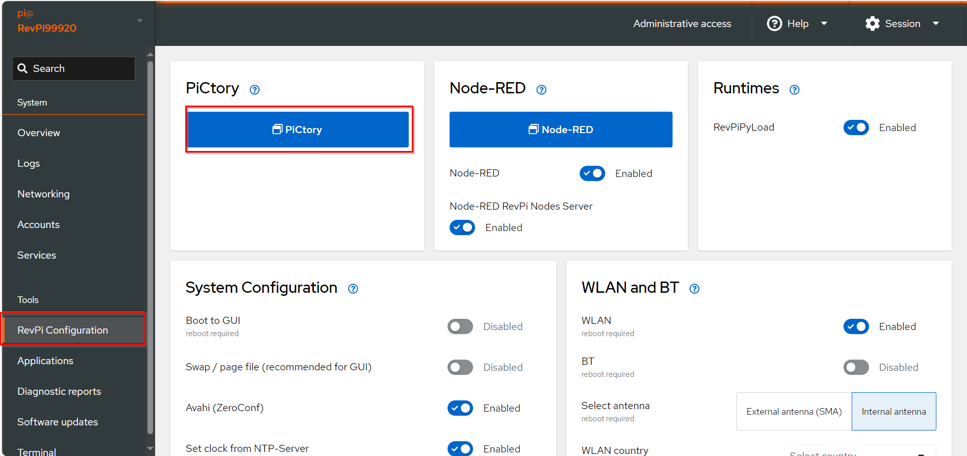
▷ Drag the base module from the Device Catalog onto the virtual DIN rail.
▷ Open the folder Virtual Devices in the Device Catalog.
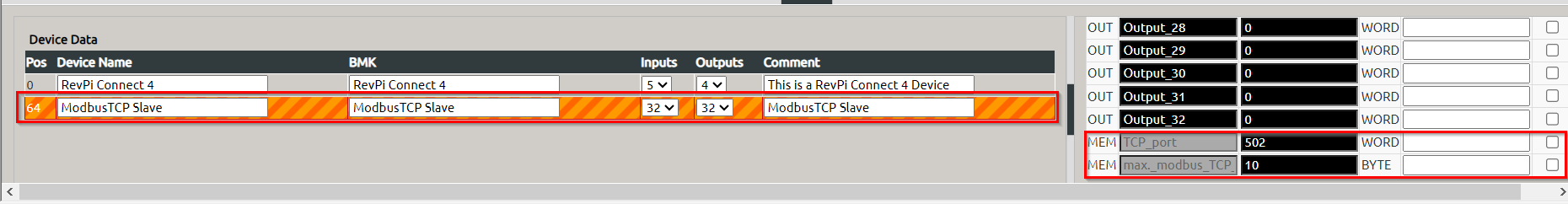
▷ Drag Modbus TCP Slave to the base module on the virtual DIN rail.
❯ The Modbus TCP Slave will now appear in the configuration
▷ Select the Modbus TCP Slave in the configuration.
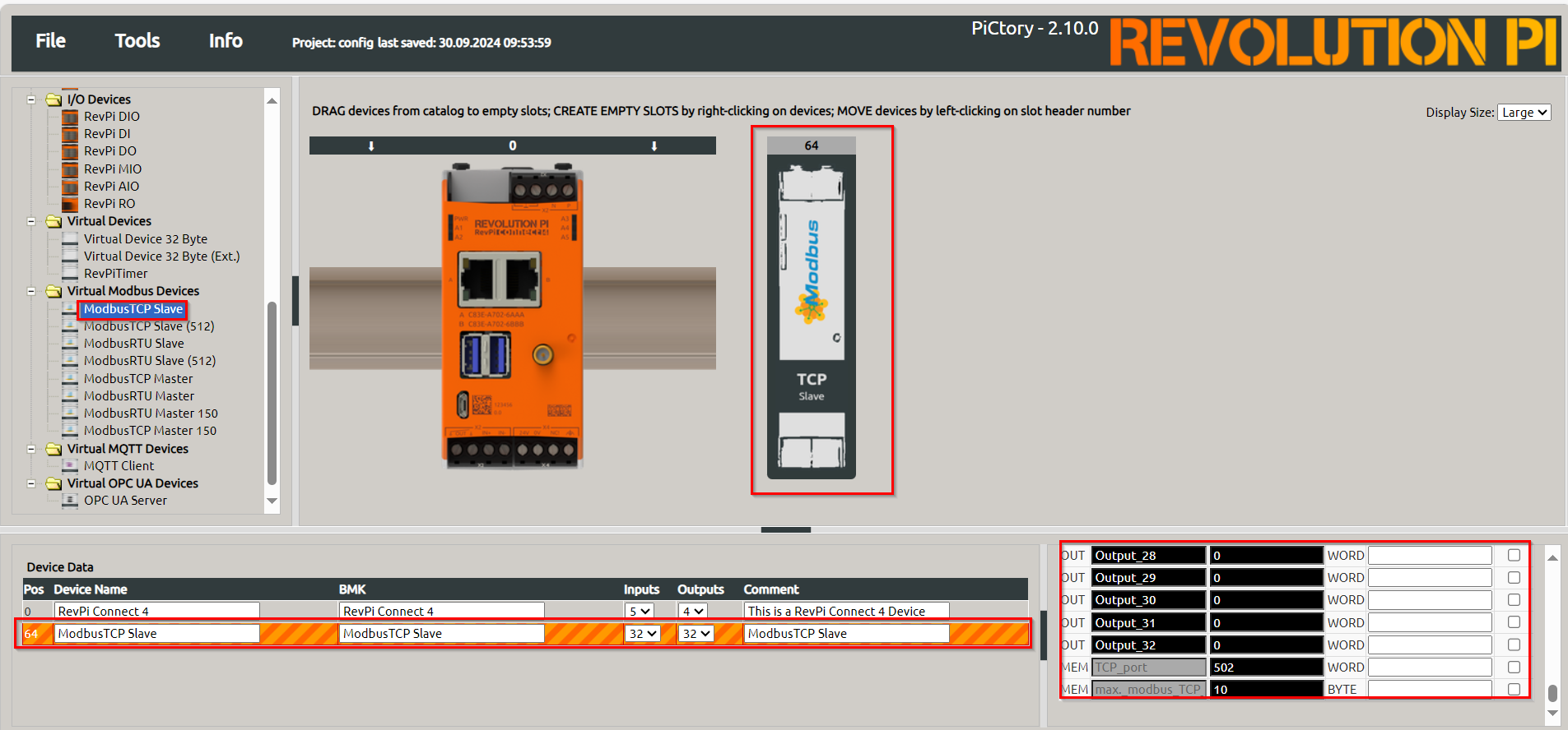
▷ Set the following parameters in the Value Editor:
-
TCP Port:
502(default value according to the Modbus specification). -
Max. Modbus TCP Connections:
10(or other suitable value).
Step 3: Querying the CPU Temperature #
The CPU temperature of the RevPi Connect can be queried using the following command in the terminal:
/usr/bin/vcgencmd measure_tempThe output will display the temperature, for example:
temp = 48.7°CTo prepare the data for Modbus processing, convert the temperature to x10 °C format using this command:
/usr/bin/vcgencmd measure_temp | awk ' { print substr($0,6,2) substr($0,9,1) } '
487
❯ This outputs the temperature in a suitable format, e.g., 487 for 48.7 °C.
Writing Data to a Modbus Register #
To write the converted temperature data into a Modbus register, use the following command:
piTest –w Output_1,$(/usr/bin/vcgencmd measure_temp | awk ' { print substr($0,6,2) substr($0,9,1) } ')For continuous updates, run the process in a loop:
while true; do piTest -w Output_1,$(/usr/bin/vcgencmd measure_temp | awk ' { print substr($0,6,2) substr($0,9,1) } '); sleep 1; done &Output:
Write value 492 dez (=01ec hex) to offset 11.
Write value 498 dez (=01f2 hex) to offset 11.
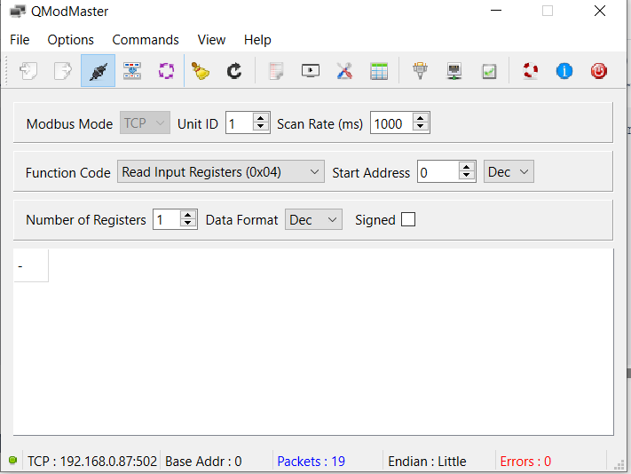
Write value 492 dez (=01ec hex) to offset 11.Step 4: Querying Data Using qModMaster #
▷ Download and install qModMaster on a Windows PC.
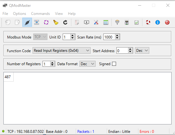
▷ Set the following parameters:
-
Modbus Mode: TCP
-
Unit ID:
1 -
Scan Rate (ms):
1000 -
Function Code: Read Input Registers (0x04)
-
Start Address:
0 -
Number of Registers:
1 -
Format: Decimal
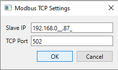
Configure qModMaster
▷ Select .
▷ Enter the IP address of the RevPi Connect in the Slave IP field.
▷ Set the TCP port to 502 (default for ModbusTCP connections).
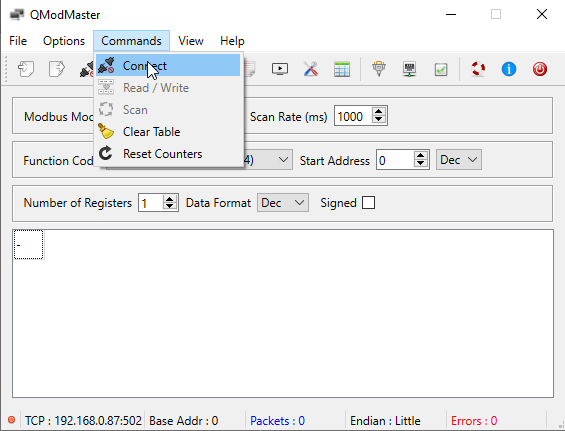
Connect to the Modbus
▷ Click on to establish a connection with the Modbus Slave.
Query Data
▷ Click on to retrieve data.
▷ The CPU temperature will be displayed in decimal form, e.g., 487 for 48.7°C.
Modbus Functions #
The Modbus slave module supports the following Modbus functions:
| Function | Description |
|---|---|
Read Holding Registers (0x03) |
Read input data. |
Read Input Registers (0x04) |
Read output data. |
Write Single Register (0x06) |
Write to a single input register. |
Write Multiple Registers (0x10) |
Write to multiple input registers. |