The RevPi base module can act as a Modbus RTU Master, enabling you to connect and communicate with various Modbus RTU slaves such as temperature sensors, push-buttons, and motion detectors. This guide walks you through setting up and configuring your RevPi as a Modbus RTU Master for robust industrial communication.
Prerequisites #
Preparation #
For USB Connection (RevPi Core or RevPi Connect) #
-
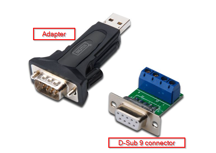
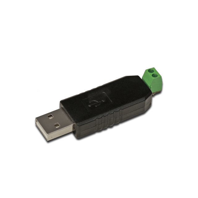
Connect a USB port of the RevPi base module to the adapter.
-
Use a D-Sub 9 socket to connect the adapter to the slave devices.
-
Specify the address of the slaves and make a note of it. If necessary, you can find information on this in the manufacturer’s operating instructions.
|
Note
|
If you are using several slaves, you have to make sure that each slave has its own address. If 2 or more slaves have the same address, communication errors occur |
| Signal | Sub-D Pin |
|---|---|
RS485- |
1 |
RS485+ |
2 |
GND |
5 |
+5V |
6 |
Some USB-Serial adapters might only have RS485 data signal lines (D+ and D-).
For RS485 Terminal (RevPi Connect/Connect 4) #
RevPi Connect models come equipped with an RS485 screw-type terminal for direct connection. The terminal features:
-
A (+): Positive RS485 line.
-
B (-): Negative RS485 line.
-
GND: Ground.
-
Functional Earth: Ensures signal integrity.
Ensure correct wiring for robust and cost-effective integration of RS485 devices.
The socket has common A/B line terminals (better marked than D+ and D-) and reference terminals (internal GND and functional earth via 1 MOhm RC network).
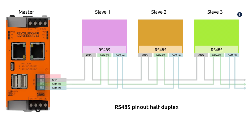
Wiring example for RevPi Connect:
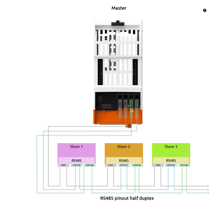
Wiring example for RevPi Connect 4
Step 1: Configure Hardware Connections #
-
Connect the RS485 Network:
Wire the A (+) and B (-) lines from the RevPi RS485 terminal (or USB-RS485 adapter) to the slave devices. -
Assign Unique Slave Addresses:
Each slave must have a unique address. Refer to the device’s manual to configure the address.
|
Note
|
Duplicate slave addresses will result in communication errors. |
Step 2: Configure Modbus RTU Master in PiCtory #
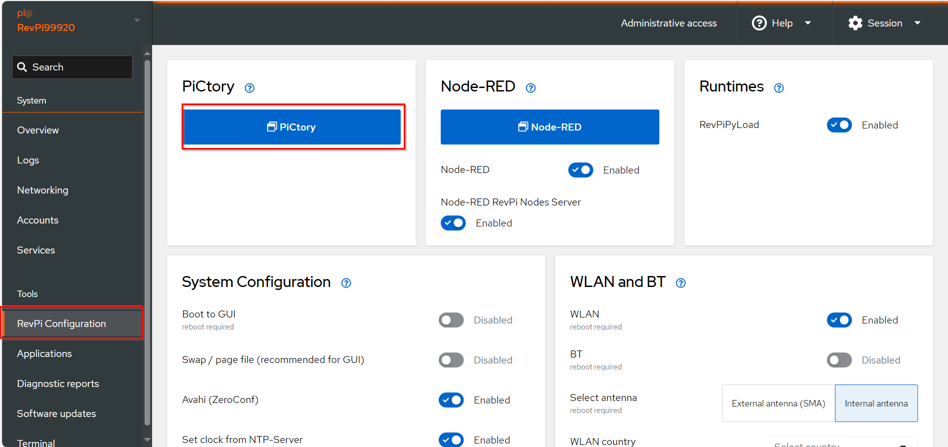
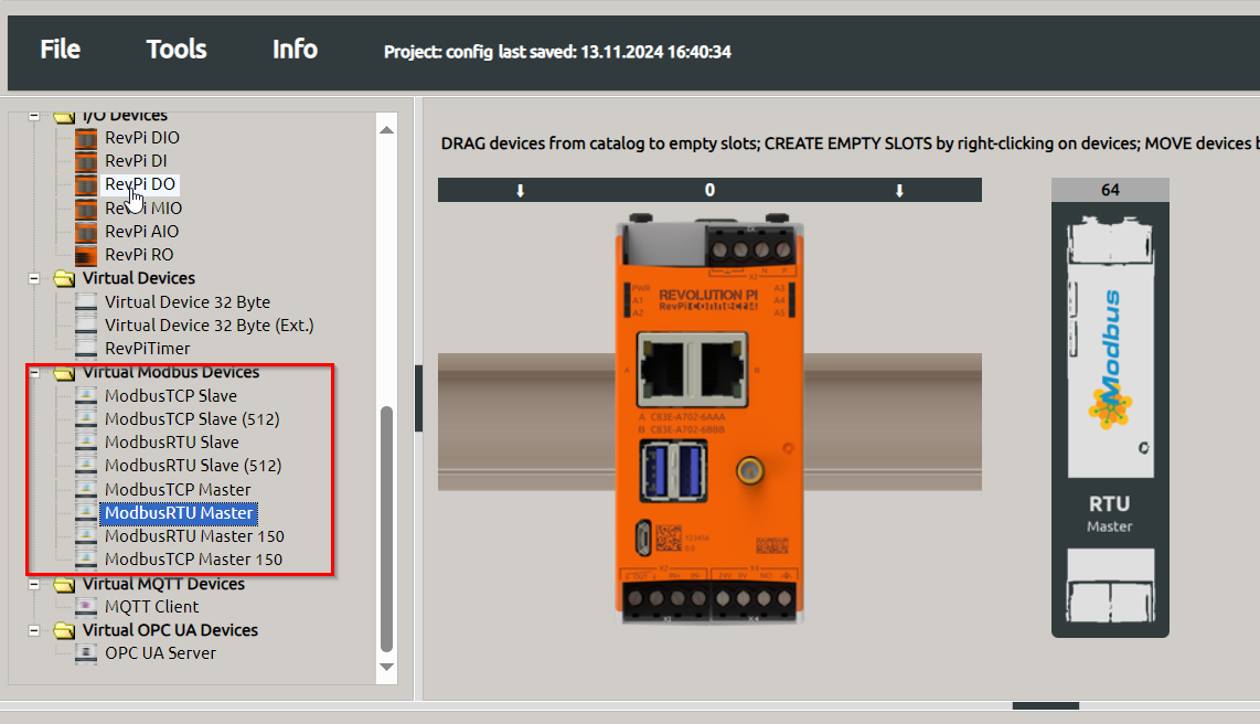
▷ Drag the base module from the Device Catalog onto the virtual DIN rail.
▷ Open the folder Virtual Devices in the Device Catalog.
-
Drag Modbus RTU Slave to the base module on the virtual DIN rail.
❯ The Modbus RTU Master will now appear in the configuration
- Select the Modbus RTU Master in the configuration.
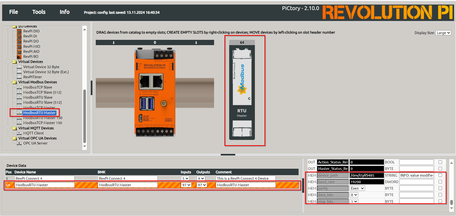
-
Set the following parameters in the Value Editor:
| Parameter | Description |
|---|---|
Input |
Configure up to 32 input values (16 bits each) |
Output |
Configure up to 32 output values (16 bits each) |
device_path |
Path to the Linux device file (default: |
baud_rate |
Speed of the serial connection (default: |
parity |
Parity bit configuration: None, Even (default), Odd |
data_bits |
Number of data bits (default: |
stop_bits |
Number of stop bits (default: |
|
Note
|
Configure udev rules for consistent device file paths when using multiple devices of the same type. |
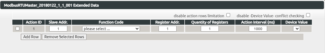
Step 3: Configure Modbus Commands #
-
Open Extended Data:
▷ Right-click on the Modbus RTU Master in the configuration and select Extended Data. -
Add Modbus Commands:
❯ In the input mask, define commands to communicate with the slave:
| Parameter | Description |
|---|---|
Slave Addr. |
Unique address of the slave device. May be assigned only once. |
Function Code |
Modbus function (e.g., READ_HOLDING_REGISTERS, WRITE_SINGLE_REGISTER). |
Register Address |
Address of the Modbus register or bit (check slave documentation). |
Quantity |
Number of registers/bits to read or write. |
Action Interval |
Interval between commands (in milliseconds). |
Device Value |
Variable name in the RevPi process image for the first word/bit of the command. |
|
Note
|
|
-
Save and Reset:
▷ Click .
▷ Click to apply the configuration.
Troubleshooting and Error Codes #
If errors occur, check the Modbus_Master_Status register for the error code:
| Error Code | Meaning |
|---|---|
|
Device not found. Check wiring. |
|
Device does not respond. Verify configuration and register address. |
|
ILLEGAL FUNCTION: Invalid function code. |
|
ILLEGAL DATA ADDRESS: Invalid or write-protected register address. |
|
INVALID CRC: Corrupted packet. Check wiring and connections. |
|
CONNECTION TIMED OUT: Slave did not respond. |
To reset an error, manually write 1 to the Master_Status_Reset or Action_Status_Reset register.
Notes and Best Practices #
-
Use a higher Action Interval for heavy system loads to prevent communication delays.
-
Extend Modbus RTU Master capacity by adding more masters for additional values.