Objective: Use a RevPi base module as a Modbus RTU Server so that a Modbus RTU Client can read data from or write data to the RevPi. The configuration is performed in the RevPi application PiCtory.
Using the RevPi as a Modbus RTU Server is suitable for scenarios where a higher-level Modbus RTU Client needs to exchange process data with the RevPi via a serial RS485 connection.
This tutorial applies to all RevPi base modules. Base modules without a built-in RS485 interface can be connected using a USB-to-RS485 adapter.
Prerequisites #
Devices
✓ Modbus RTU Client, e.g., QModMaster on a Windows PC
✓ Optional: USB-RS485 adapter on the Windows PC if QModMaster is used.
✓ Optional: USB-RS485 adapter on the RevPi if no RS485 interface is available.

Hardware Installation
✓ The RevPi base module is connected to the network.
✓ The RevPi base module is connected to the power supply.
✓ The Modbus RTU Client is connected to the RevPi via the RS485 interface or a USB-RS485 adapter.
| Signal | Pin |
|---|---|
RS485- |
D+ |
RS485+ |
D- |
See also:
-
RevPi Connect 5: RS485 Serial Interface
-
RevPi Connect 4: RS485 Serial Interface
-
RevPi Connect S/SE: RS485 Serial Interface
-
RevPi Flat S: RS485 Serial Interface
Software Installation
✓ Web browser (e.g., Chrome, Firefox, or Edge)
✓ QModMaster from SourceForge is installed on your Windows PC.
✓ RevPi and Modbus RTU Client are on the same network.
✓ The address, baud rate, parity, data bits, and stop bits of the Modbus RTU Server are defined.
1. Configuring the Modbus RTU Server in PiCtory #
▷ Start PiCtory.
▷ Drag the RevPi base module from the Device Catalog to the empty slot in the configuration area with position number 0.
▷ Drag a Modbus RTU Server from Virtual Modbus Devices in the Device Catalog to the base module in the configuration area.
❯ The Modbus RTU Server is now displayed in the configuration area.

▷ Select the Modbus RTU Server in the configuration area.
▷ Configure the following parameters at the very bottom of the list in the Value Editor:
| Parameter | Description |
|---|---|
Input_ |
Up to 32 input values, each 16 bits wide. Values are written by the Modbus RTU Client and can be read in the process image. |
Output_ |
Up to 32 output values, each 16 bits wide. Values can be read by the Modbus RTU Client. |
device_path |
Path to the Linux device file. |
baud_rate |
Speed of the serial connection. |
parity |
Parity bit configuration: |
data_bits |
Number of data bits. |
stop_bits |
Number of stop bits. |
modbus_address |
Address of the Modbus RTU Server on the RS485 bus. |
|
Note
|
Configure |
▷ In the Value Editor, you can optionally assign suitable I/O names for easier reference, e.g., Modbus_Input_1.
See also Configuring Values.
▷ Select to save the configuration.
▷ Select to apply the configuration.
2. Setting Up the Modbus RTU Client #
Configuring QModMaster
▷ Open QModMaster.
▷ Set the following parameters in the main window:
-
Modbus Mode: RTU
-
Slave Addr: value from modbus_address
-
Scan Rate (ms):
1000 -
Function Code: Write Multiple Registers (0x10)
-
Start Address:
0 -
Number of Registers:
3 -
Data Format: Dec
▷ Enter values in the Modbus registers, e.g., 1, 2, and 3.
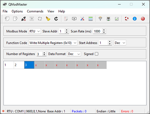
▷ Select .
▷ Set the serial parameters to match the Modbus RTU Server configuration in PiCtory:
-
Serial port: COM port of the USB-RS485 adapter
-
Baud: value from baud_rate
-
Data Bits: value from data_bits
-
Stop Bits: value from stop_bits
-
Parity: value from parity
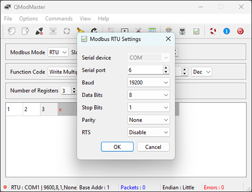
Starting Serial Communication
▷ Select to start communication with the Modbus RTU Server.
▷ Select to write the values to the Modbus registers.
3. Checking Data in the Process Image #
▷ Open a terminal.
▷ Query the written values with piTest:
piTest -1 -r Input_1
piTest -1 -r Input_2
piTest -1 -r Input_3
❯ Output:
2 Byte-Value of Input_1: 1 dec (=0001 hex)
2 Byte-Value of Input_2: 2 dec (=0002 hex)
2 Byte-Value of Input_3: 3 dec (=0003 hex)
Values that a Modbus RTU Client writes to the registers starting at address 0 are stored in the RevPi process image under Input_*.
Modbus Functions #
The Modbus server module supports the following Modbus functions:
-
Read Holding Registers (0x03)
-
Read Input Registers (0x04)
-
Write Single Register (0x06)
-
Write Multiple Registers (0x10)