This tutorial demonstrates how to configure Modbus TCP and Modbus RTU masters on a RevPi Connect+ with CODESYS Control CODESYS Control for Linux ARM or ARM64. The application reads the holding registers (0—9) of connected Modbus slaves and writes their values back to holding registers (10—19).
Prerequisites #
Hardware #
✓ RevPi Connect+
✓ One Modbus TCP slave
✓ One Modbus RTU slave
For detailed instructions about how to set up your system, see Getting Started.
Software #
✓ CODESYS Development System installed on your PC
To ensure a compatible system with suitable software, see CODESYS System Requirements.
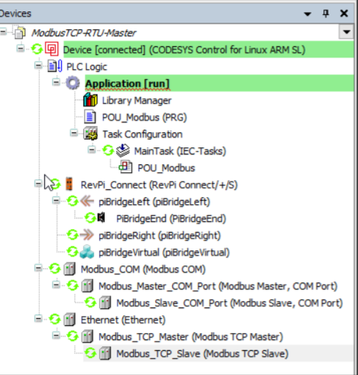
Overview #
The device tree in CODESYS is configured with:
-
Modbus TCP Master: Reads and writes to a TCP slave device.
-
Modbus RTU Master: Communicates with a serial RTU slave device.
-
POU_Modbus: Handles the application logic for reading and writing data.
Adapting for RevPi Core or RevPi Compact
To adapt the project for RevPi Core or RevPi Compact:
▷ Right-click on RevPi Connect in the CODESYS device tree.
▷ Select Update device.
▷ Choose RevPi Core or RevPi Compact as the replacement and rename the device accordingly.
Step 1: Configuring Modbus RTU Serial Port #
For RevPi Connect or RevPi Core
-
Edit the configuration file:
sudo nano /etc/CODESYSControl_User -
Add the following line:
[SysCom] Linux.Devicefile=/dev/ttyUSB -
Map the COM ports in CODESYS as follows:
-
/dev/ttyUSB0 → COM port 1
-
/dev/ttyUSB1 → COM port 2
-
/dev/ttyUSBn → COM port n
If an extra USB-485 converter is connected, the correct COM port has to be identified.
+ image::revpi-tutorial-codesys-modbus-tcp-rtu-master-2.png[Project Setting]
-
For RevPi Compact
-
Default RS485 Port:
▷ Edit/etc/CODESYSControl_Userand add:[SysCom] Linux.Devicefile=/dev/ttyAMA -
Using USB-485 Converter:
▷ Add the following line instead:
   [SysCom]
   Linux.Devicefile=/dev/ttyUSB
Step 2: Configuring Modbus RTU Slave #

-
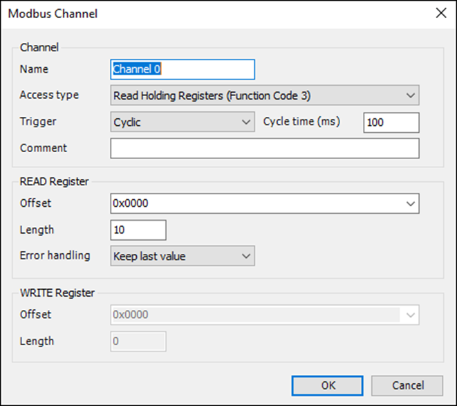
Set up the RTU slave with:
-
Channel 1: Read Holding Registers
-
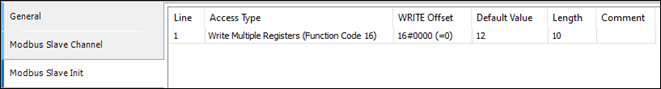
Channel 2: Write Multiple Registers
-
-
Ensure the default values for the first 10 holding registers are 12.
-
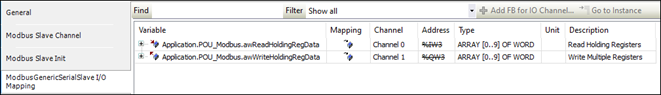
Map these channels in the POU_Modbus logic for application-level access.
Step 3: Configuring Modbus TCP Slave #
-
Specify the Modbus TCP Slave Address in the CODESYS configuration.
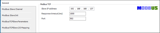
-
Use the same mapping logic as Modbus RTU for holding registers 0—9 and 10—19.
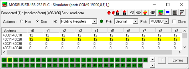
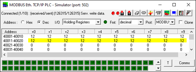
Step 4: Simulating Modbus Slaves #
To simulate Modbus TCP and RTU slaves, use ModRSsim2:
-
Download the application from ModRSsim2 on SourceForge.
-
Configure Modbus TCP/RTU slaves to have holding registers:
-
40001—40010 for source data
-
40010—40020 for destination data
-
Step 5: Deploy and Test #
-
Download the compiled project to the RevPi device.
-
Run the application on your RevPi base module.
-
Verify that:
-
Data is correctly read from holding registers 0—9.
-
Data is written back to holding registers 10—19.
-
|
Note
|
Default RTU Slave Configuration |
|
Note
|
Debugging |
|
Note
|
Simulation |
This setup allows Modbus TCP and RTU masters to operate simultaneously, enabling robust data exchange with Modbus-enabled devices.