Product Description #
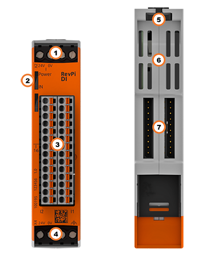
The RevPi DI is an expansion module of the Revolution Pi product family with 16 digital inputs.
Components #
| Position | Component | Application |
|---|---|---|
1 |
X2 connector |
|
2 |
2 × status LED |
|
3 |
16 × digital input |
Pinout, |
4 |
X4 connector |
|
5 |
Locking clamps |
|
6 |
Ventilation Slots |
|
7 |
2 × PiBridge |
Pinout #
The RevPi DI has 16 GPIO interfaces as inputs.
Pins 1 to 16 on the connector are assigned as follows:
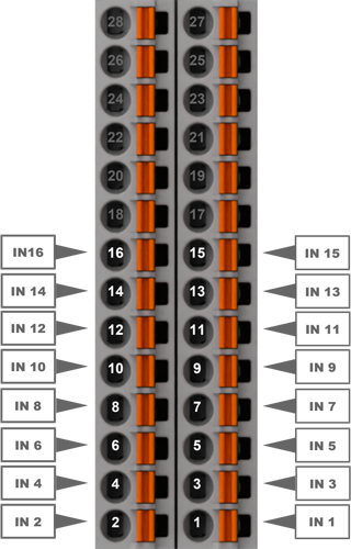
Pins 17 to 28 are not assigned and cannot be used.
For the configuration, see Configuring RevPi DI in the PiCtory Value Editor.
LEDs #
The LEDs indicate different device statuses.
Power #
| Signal | Function |
|---|---|
Green |
The connection to the RevPi base module is established. |
Flashes red |
The connection to the RevPi base module is being established (initialization phase). |
Red |
The connection to the RevPi base module is interrupted. |
IN #
| Signal | Function |
|---|---|
Off |
The connection to the RevPi base module is not yet established (initialization phase). |
Green |
Inputs are ready for operation. |
Flashes red |
Error at the inputs. |
Red |
No or too low supply voltage. |
Compatible Base Modules #
-
RevPi Connect 5
-
RevPi Connect 4
-
RevPi Connect SE (left side only)
-
RevPi Connect+ (left side only)
-
RevPi Connect S (left side only)
-
RevPi Core (all variants)
Scope of Delivery #
The scope of delivery includes
-
RevPi expansion module
-
PiBridge plug connector
-
X2 connector
-
X4 connector
-
2 × 14-pin I/O module
-
2 × blind plug for PiBridge
-
Supplement
Mounting and Connecting #
The RevPi was developed for use in a control cabinet. Observe the specifications for the Intended Use and all Safety Instructions.
|
Warning
|
Danger to life due to electrical shock
There is a risk of fatal electrical shock when working on devices in the switch cabinet with 230 V mains voltage. ▷ Operations in the switch cabinet may only be carried out by qualified electricians. ▷ Before carrying out any operations in the switch cabinet, switch off the power supply properly. |
Carry out the mounting and connection in the following order:
-
Mount the RevPi base module and all expansion modules on a DIN rail.
-
Connect the expansion module via the PiBridge plug connector.
-
Connect all other devices such as sensors and actuators.
-
As last step connect the power supply for the RevPi DI and for the digital inputs.
Connecting the Power Supply #
Power supply Connection RevPi DI #
The power supply of the RevPi DI requires cabling via the X4 connector, see Connecting the Power Supply.
This power supply can be provided via the X4 connector of the RevPi base module from the same power source. The RevPi DI requires 1.5 W.
Power Supply Connection Inputs via X2 #
|
Important
|
Damage to the device due to different grounding
▷ Refer all connections to the same system ground. ▷ Connect external voltage inputs or outputs with different grounding externally. |
The connected devices can be supplied with 12 … 24 V directly via the RevPi DI. A maximum of 12 W additional power may be used per connection. This power supply requires cabling via the X2 connector:
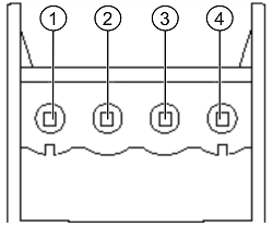
| Pin | Function |
|---|---|
1 |
24 V supply for the inputs |
2 |
Ground for the inputs |
3 |
— |
4 |
— |
Configuration #
The RevPi expansion modules are configured via the System Configuration with PiCtory.
Configuring RevPi DI in PiCtory #
The RevPi DI has 16 inputs for reading in signals. These can be configured in PiCtory’s Value Editor.
Mind the Pinout. Pinout
▷ Start PiCtory.
▷ Insert the RevPi DI from the Device Catalog > I/O Devices into the correct slot in the Revolution Pi system on the Configuration Board.
▷ If necessary, adjust the basic configuration of the RevPi DI under Device Data.
▷ Configure the settings In the Value Editor (see below).
▷ Save the configuration via File > Save as Start-Config..
▷ Restart the driver via Tools > Reset Driver.
INP Input Values #
| Field | Offset | Description |
|---|---|---|
I_1 … 16 |
Offset: 0 |
Shows the current values of the inputs 1 … 16 (bits 0 … 15). |
Status |
Offset: 4 |
Displays the status of the expansion module: |
Counter_1 … 15 |
Offset: 6 |
Optionally, configure the inputs as encoders and activate counter function. |
MEM Memory Values #
| Parameter | Offset | Description |
|---|---|---|
InputMode_1 … 16 |
Offset: 88 |
Select the mode for each input. |
InputDebounce |
Offset: 104 |
Set the debounce filter time for all inputs. |
Configuring Counter #
Optionally set a counter function for each input, e.g. how often a button has been pressed. A 32-bit value is entered in the process image for each counter. The current counter value is returned as signed 32-bit value.
Configuring Encoder #
Two inputs together can be configured as encoders (rotary encoders), e.g. to control parts of quantities in combination with the PWM function. A maximum of five encoders per RevPi DI can be used.
The inputs must always be used in pairs, starting with an odd-numbered input, e.g. input 1 and 2 or input 3 and 4.
▷ Set the value to Encoder under MEM InputMode . The subsequent input is thus automatically also configured as an Encoder.
❯❯ The current encoder value is returned as signed 32-bit value in the first input.