RevPi DIO
Product Description
The RevPi DIO is an expansion module of the Revolution Pi family and has 14 digital inputs and 14 digital outputs for connecting actuators and sensors.
Components
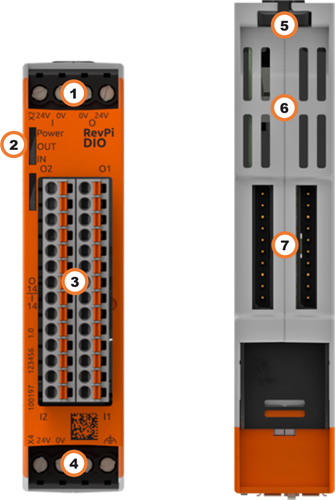
| Position | Component | Application |
|---|---|---|
| 1 | X2 connector | Connecting the Power Supply |
| 2 | 3 × status LED | LEDs |
| 3 | 14 × digital input/output | Pinout, Digital Inputs and Outputs |
| 4 | X4 connector | Connecting the Power Supply |
| 5 | Locking clamps | Mounting the Device on a DIN Rail |
| 6 | Ventilation Slots | Mounting the Device on a DIN Rail |
| 7 | 2 × PiBridge | Connecting Expansion Modules |
Pinout
The RevPi DIO has 28 GPIO interfaces, including 14 inputs and 14 outputs.
The pins on the connector are assigned as follows:
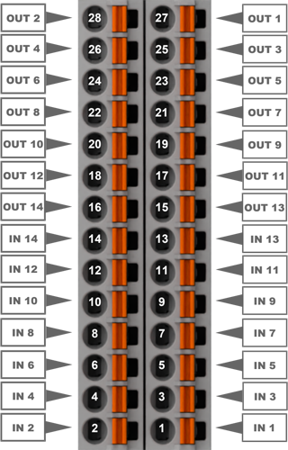
For the configuration, see Configuring RevPi DIO in the PiCtory Value Editor .
LEDs
The LEDs indicate different device statuses.
Power
| Signal | Function |
|---|---|
| Green | The connection to the RevPi base module is established. |
| Flashes red | The connection to the RevPi base module is being established (initialization phase). |
| Red | The connection to the RevPi base module is interrupted. |
OUT
| Signal | Function |
|---|---|
| Off | The connection to the RevPi base module is not yet established (initialization phase). |
| Green | Outputs are ready for operation. |
| Flashes red | Error at the outputs. |
| Red | No or too low supply voltage. |
IN
| Signal | Function |
|---|---|
| Off | The connection to the RevPi base module is not yet established (initialization phase). |
| Green | Inputs are ready for operation. |
| Flashes red | Error at the inputs. |
| Red | No or too low supply voltage. |
Compatible Base Modules
- RevPi Connect 5
- RevPi Connect 4
- RevPi Connect SE (left side only)
- RevPi Connect+ (left side only)
- RevPi Connect S (left side only)
- RevPi Core (all variants)
See Rules for the Arrangement of Devices.
Scope of Delivery
The scope of delivery includes
- RevPi expansion module
- PiBridge connector
- X2 connector
- X4 connector
- 2 × 14-pin I/O module
- 2 × cover plug for PiBridge
Mounting and Connecting
The RevPi was developed for use in a control cabinet. Observe the specifications for the Intended Use and all Safety Instructions.
Danger to life due to electric shock
There is a risk of fatal electric shock when working on devices in the switch cabinet with 230 V mains voltage.
▷ Work in the switch cabinet may only be carried out by qualified electricians.
▷ Before carrying out any work in the switch cabinet, switch off the power supply properly.
Carry out the mounting and connection in the following order:
-
Mount the RevPi base module and all expansion modules on a DIN rail.
-
Connect the expansion module via the PiBridge connector.
-
Connect all other devices such as sensors and actuators.
-
As last step connect the power supply for the RevPi DIO and for the inputs and outputs.
Connecting the Power Supply
Power supply Connection RevPi DIO
The power supply of the RevPi DIO expansion module requires cabling via the X4 connector, see Connecting the Power Supply . Connecting the Power Supply
This power supply can be provided via the X4 connector of the RevPi base module from the same power source. The RevPi DIO requires 1.5 W plus the power consumption of the connected sensors and actuators.
Power supply Connection Inputs and outputs
Damage to the device due to different grounding
▷ Refer all connections to the same system ground.
▷ Connect external voltage inputs or outputs with different grounding externally.
The power supply for the inputs and outputs on the RevPi DIO requires cabling via the X2 connector. Inputs and outputs are galvanically isolated. Connected sensors and actuators can be supplied with 12 ... 24 V directly via the inputs and outputs of the RevPi DIO. A maximum of 12 W additional power may be used per connection.
| Pin | Function | X2 connector |
|---|---|---|
| 1 | 24 V supply for the outputs | 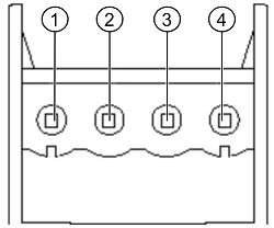 |
| 2 | Ground for the outputs | |
| 3 | Ground for the inputs | |
| 4 | 24 V supply for the inputs |
Configuration
The RevPi expansion modules are configured via the System Configuration with PiCtory.
Configuring RevPi DIO in PiCtory
The RevPi DIO has 28 GPIO interfaces, 14 inputs and 14 outputs, for reading in and outputting signals. These can be configured in PiCtory’s Value Editor.
Mind the Pinout.
▷ Start PiCtory.
▷ Insert the RevPi DIO from the Device Catalog > I/O Devices into the correct slot in the Revolution Pi system on the Configuration Board.
▷ If necessary, adjust the basic configuration of the RevPi DIO under Device Data.
▷ Configure the settings In the Value Editor (see below).
▷ Save the configuration via File > Save as Start - Config.
▷ Restart the driver via Tools > Reset Driver.
INP Input Values
| Parameter | Offset | Beschreibung |
|---|---|---|
| I_1 … 14 | Offset: 0 | Shows the current values of the inputs (bits 0 ... 13). I_15 and I_16 are not used. With data schema 19, all values are displayed in a 16-bit value Input (see PiCtory Device Data). |
| Output_Status | Offset: 2 | Displays the current status of outputs 1 ... 14 (bits 0 ... 13). 1: Error at the output (overtemperature, overload, etc.) 0: no error |
| Status | Offset: 4 | Displays the status of the extension module. Bit 0: No communication to the input IC Bit 1: Undervoltage UV1 <7 V input 1 … 8 Bit 2: Undervoltage UV2 <14 V input 1 … 8 Bit 3: Overtemperature >135 °C input 1 … 8 Bit 4: Undervoltage UV1 <7 V input 9 … 16 Bit 5: Undervoltage UV2 <14 V input 9 … 16 Bit 6: Overtemperature >135 °C input 9 … 16 Bit 7: Error message input module Bit 8: No communication to the output IC Bit 9: CRC error on output IC Bit 10: Error message output module Bit 11 … 15; – |
| Counter_1 … 15 | Offset: 6 | Optionally, configure the inputs as encoders and activate counter function. |
OUT Output Values
| O_1 … 14 | Offset: 70 | Bits 0 ... 13 show the current values of outputs 1 ... 14.With data schema 17, all values are displayed in a 16-bit value Output (see PiCtory Device Data). |
| PWM_1 … 14 | Offset: 72 | Current PWM values in % for outputs 1 … 14. Only valid if the PWM function is enabed for the respective output. |
MEM Memory Values
| InputMode_1 … 14 | Offset: 88 | Select the mode for each input.Direct: Current value at the input is displayed.Counter, rising edge: Rising edges are counted at the input.Counter, falling edge: Falling edges are counted at the input.Encoder: Use inputs as encounters. |
| InputDebounce | Offset: 104 | Set the debounce filter time for all inputs. |
| OutputPushPull | Offset: 106 | Operate outputs in pushpull or highside mode. |
| OutputOpenLoadDetect | Offset: 108 | Activate / deactivate open-load detection. |
| OutputPWMActive | Offset: 110 | Activate outputs for PWM, see Activating PWM. |
| OutputPWMFrequency | Offset: 112 | Define PWM frequency for all outputs, see Activating PWM. |
Configuring Counter
Optionally set a counter function for each of the 14 inputs, e.g. how often a button has been pressed. A 32-bit value is entered in the process image for each counter. The current counter value is returned as signed 32-bit value.
Configuring Encounter
Two inputs together can be configured as encoders (rotary encoders), e.g. to control parts of quantities in combination with the PWM function. A maximum of five encoders per RevPi DIO can be used.
The inputs must always be used in pairs, starting with an odd-numbered input, e.g. input 1 and 2 or input 3 and 4.
▷ Set the value to Encounter under MEM InputMode . The subsequent input is thus automatically also configured as an Encounter.
❯❯ The current encoder value is returned as signed 32-bit value in the first input.
Activating PWM (Pulse Width Modulation)
Optionally, a PWM function can be activated for each of the 14 outputs. With PWM, instead of one bit per channel, a whole byte value from 0 ... 100 is output, which defines the pulse width at the output in %. The PWM function is useful for controlling parts of quantities, e.g. regulating a water supply or dimming lights.
▷ In the Value Editor under MEM OutputPWMActive , define for which of the 14 outputs the PWM should be activated.
Example: If PWM is to be activated for outputs 1 and 2, enter the decimal value 3.
❯ This means that the corresponding outputs PWM_1 and PWM_2 can now be used instead of the outputs O_1 and O_2 .
▷ Under MEM OutputPWMFrequency , specify the frequency at which the PWM signal is to be generated. A PWM frequency can be set for each RevPi expansion module:
| PWM Frequency | Duty Cycle |
|---|---|
| 40 Hz | 1% |
| 80 Hz | 2% |
| 160 Hz | 4% |
| 200 Hz | 5% |
| 400 Hz | 10% |
▷ For the outputs OUT PMW_1 ... 14 activated as PWM, enter the required PWM value in %.
▷ Save the configuration via File > Save as Start-Config. .
▷ Restart the driver with Tools > Reset Driver . As an alternative, use piTest to address the PWM outputs with the command
-w .