RevPi as Modbus TCP Master
Introduction
This tutorial explains how to use a RevPi base module as a Modbus TCP Master to connect and communicate with slave devices. It provides step-by-step guidance to set up a RevPi system for industrial communication using the Modbus TCP protocol. This tutorial is designed for industrial automation professionals, IoT developers, and enthusiasts who want to configure and use Modbus TCP communication with Revolution Pi modules. Using the RevPi as a Modbus TCP Master is ideal for scenarios where devices such as sensors, actuators, or other industrial equipment need to be controlled or monitored in a networked environment.
Prerequisites
Hardware
- RevPi base module
- Slave device(s)
- Matching cables with RJ45 connectors
- Internet connection
Software
- A modern web browser (e.g., Google Chrome or Mozilla Firefox).
System Setup
Ensure that:
- The RevPi base module and the slave devices are located on the same network.
- IP addresses of all slave devices are specified and documented as per the manufacturer's instructions.
- Each slave device has a unique IP address.
Step 1: Hardware Setup
▷ Connect the slave devices to the RevPi via the RJ45 jack.
▷ Note the IP addresses and ports of all slave devices.
Note:Avoid assigning the same IP address to multiple slave devices on the same port, as this will cause communication errors.
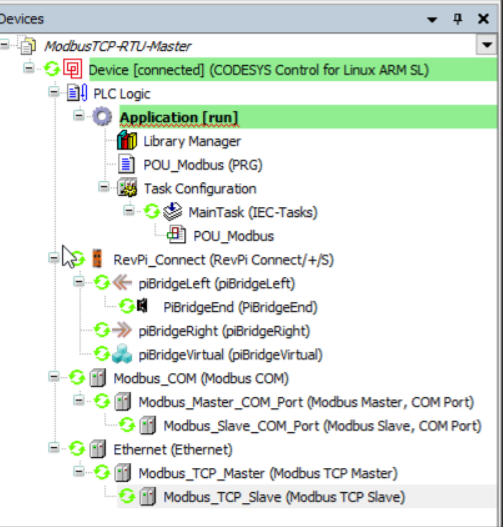
Step 2: Configure Modbus TCP Master in PiCtory
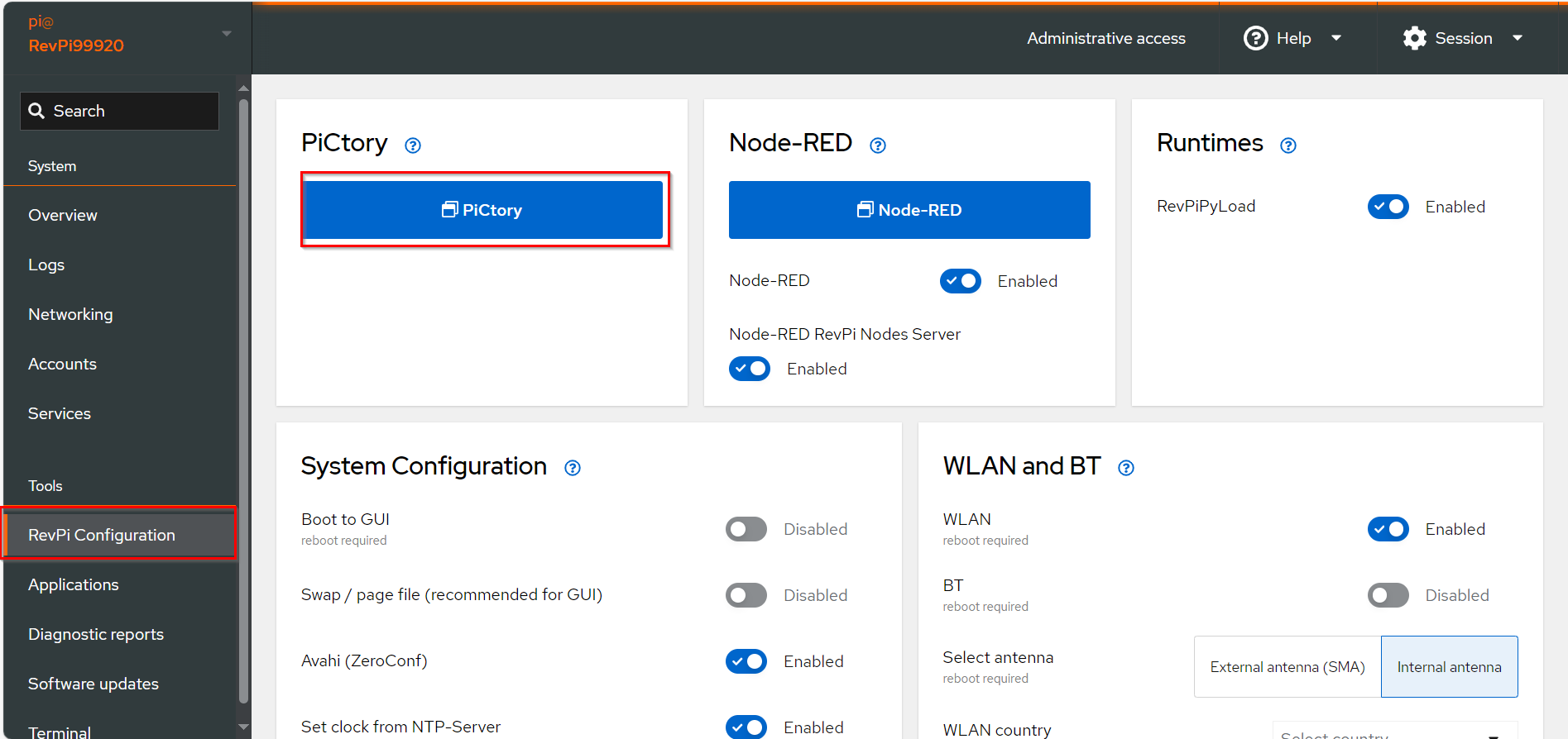
▷ Add Base Module and Add the virtual Modbus TCP Master to your configuration.
-
Drag the base module from the Device Catalog onto the virtual DIN rail.
-
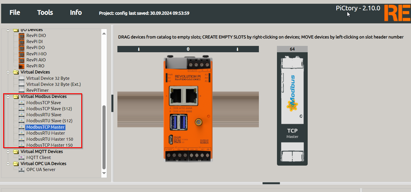
Open the folder Virtual Devices in the Device Catalog.
- Drag Modbus TCP Master to the base module on the virtual DIN rail.
➜ The Modbus TCP Master will now appear in the configuration
- Drag Modbus TCP Master to the base module on the virtual DIN rail.
-
Select the Modbus TCP Master in the configuration.
➜ In the Device Data window, optionally Assign appropriate I/O names for easier reference, e.g., 'Modbus_Input_1'
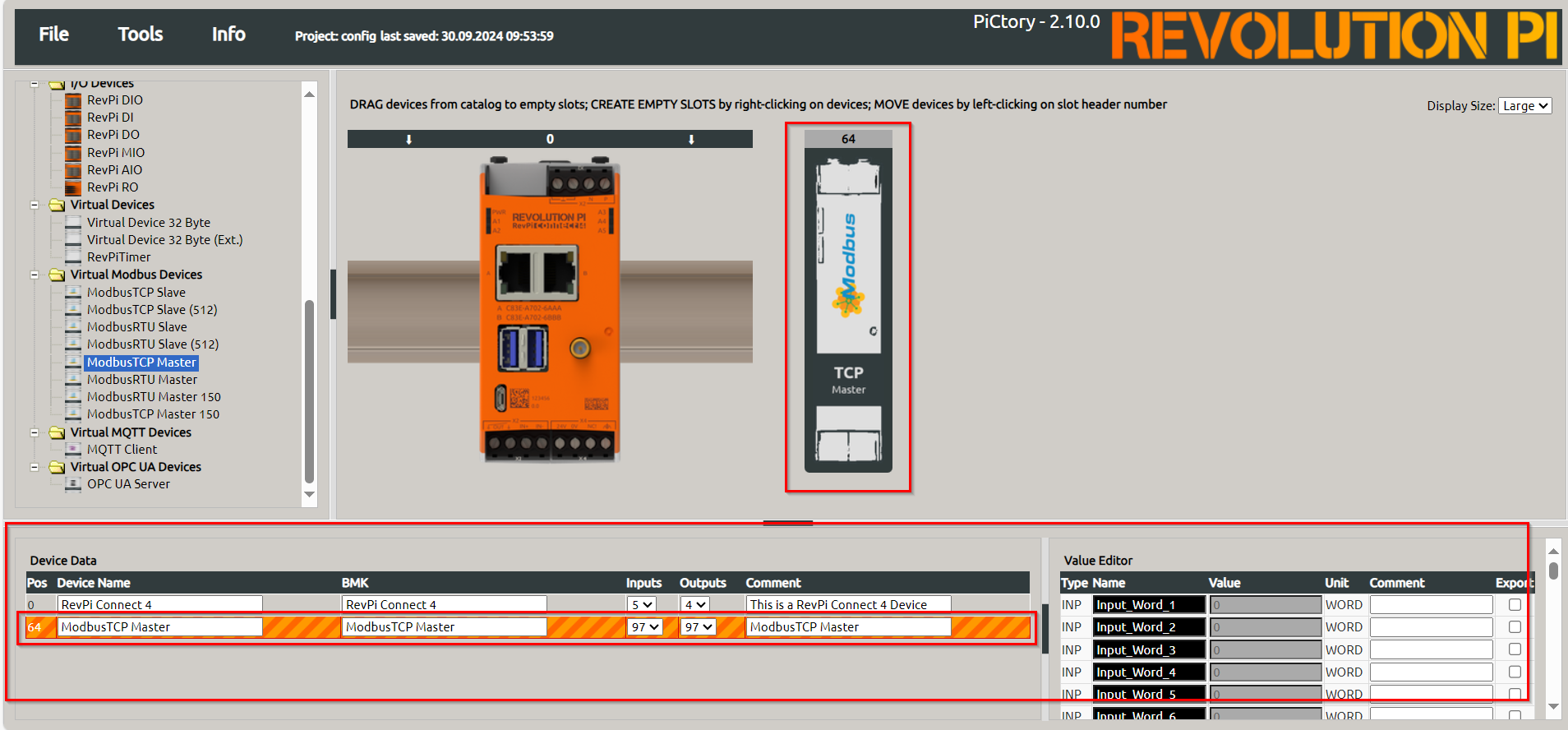
▷ Open the Value Editor and configure the following parameters:
- 'slave_IP_address': IP address of the Modbus TCP slave.
- 'slave_tcp_port': Default is '502', as specified in the Modbus specification. This can be changed if required.
▷ Save the configuration and restart the driver to apply the changes.
Step 3: Set Modbus Commands
-
Open Extended Data
▷ Right-click the Modbus TCP Master in the configuration.▷ Select Extended Data to open the command configuration interface.
-
Add Modbus Commands
▷Configure the commands using the following parameters:- Unit ID: Refer to the slave's manual for this address. Use
255if the slave ignores the address. - Function Code: Choose from the supported codes:
READ_COILS: Read single bits.READ_DISCRETE_INPUTS: Read single input bits.READ_HOLDING_REGISTERS: Read 16-bit registers.READ_INPUT_REGISTERS: Read 16-bit input registers.WRITE_SINGLE_COIL: Write a single bit.WRITE_SINGLE_REGISTER: Write a whole register.WRITE_MULTIPLE_COILS: Write consecutive bits.WRITE_MULTIPLE_REGISTERS: Write consecutive registers.
- Register Address: Define the Modbus register or bit address to access.
- Quantity of Registers: Number of registers or bits to read/write.
- Action Interval: Time interval in milliseconds for sending the command.
- Device Value: Name of the variable in the RevPi process image.

- Unit ID: Refer to the slave's manual for this address. Use
Note: For devices using 0-based addressing, increment the register address by 1 during configuration.
-
Save Configuration
▷ File > Save to save the settings.▷ Tools > Reset Driver to activate the configuration
Step 4: Troubleshooting
If communication errors occur, check the Modbus_Master_Status register for error codes. Common codes include:
0x10: Device not found (check wiring).0x11: Device does not respond or invalid register address.110: Connection timed out.
- For further details, refer to the official Modbus specification.
- Ensure proper wiring and configuration to minimize connection and communication issues.
- To resolve errors:
- Verify IP addresses and wiring.
- Ensure no overlapping Modbus commands.
Modbus Master Task Management and Error Codes
The Modbus master can handle up to 32 tasks. Each task has a corresponding register for status and status reset. If an error occurs in a task, the error code is written to the Modbus register:
Modbus_Action_Status_[1…32].
The error remains in this register until the value 1 is manually written to the corresponding reset register:
Action_Status_Reset_[1…32].
The error codes correspond to the Modbus exception codes as defined in the Modbus specification.
Error Codes Table
The table below summarizes the most important error messages:
| Error Code | Name | Description |
|---|---|---|
| 1 | ILLEGAL FUNCTION | The function code used is not allowed. Check if you are using the correct function code. |
| 2 | ILLEGAL DATA ADDRESS | The Modbus register address used is not valid. The register is either write-protected or invalid. Check the register address. |
| 3 | ILLEGAL DATA VALUE | At least one part of the data values used is invalid. For example, you may have entered too many registers. Check your values. |
| 13 | INVALID DATA | The slave has answered an incomplete packet. This can happen after a connection interruption. Check your wiring. |
| 110 | CONNECTION TIMED OUT | The slave did not respond fast enough or not at all. Check your configuration and wiring. |
Example: Temperature Measurements with RevPi as Modbus TCP Master
Hardware Setup
The temperature sensor Inveo NANO TEMP serves as the Modbus slave in this example.
Configuration Details
Refer to the sensor's manual for the following data:
| Parameter | Value |
|---|---|
| IP Address | 192.168.0.103 |
| Port | 502 |
| Modbus Register | 4004 |
| Modbus Function | READ_HOLDING_REGISTERS |
| Slave Address | 1 |
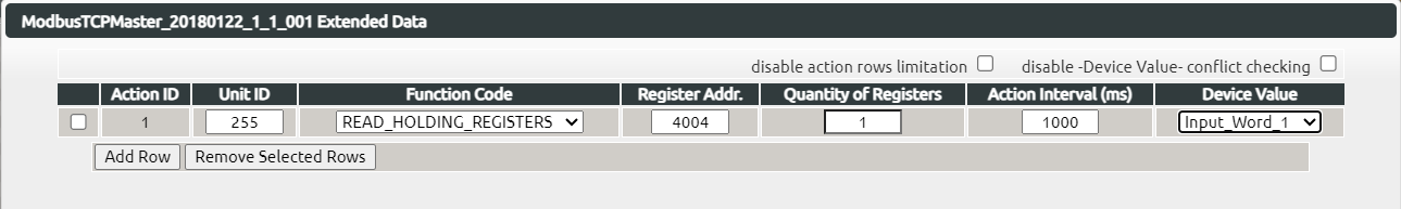
Define Modbus Commands
In the Extended Data interface, configure:
- Slave Addr.:
1 - Function Code:
READ_HOLDING_REGISTERS - Register Addr.:
4004 - Quantity of Registers:
1 - Action Interval (ms):
1000 - Device Value:
Input_Word_1
Query Data
- Save the configuration and reset the driver.
- Open a command line and run:
piTest -r Input_Word_1
➜ You receive the data of your slave:
2 Byte-Value of Input_Word_1: 284 dez (=011c hex)
The value 284 corresponds to 28.4 °C
Further Resources
Step 2: Adapting for RevPi Core or Compact