RevPi MIO
Product Description
The RevPi MIO is an expansion module of the Revolution Pi family and has 8 analog inputs, 8 analog outputs and 4 digital channels, which can be configured as digital inputs or digital outputs via software.
Components
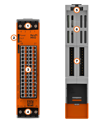
| Position | Component | Application |
|---|---|---|
| 1 | X2 connector | Digital Inputs and Outputs |
| 2 | 3 × status LED | LEDs |
| 3 | 8 × analog input 8 × analog output | Pinout, Analog Inputs, Analog Outputs |
| 4 | X4 connector | Connecting the Power Supply |
| 5 | Locking clamps | Mounting the Device on a DIN Rail |
| 6 | Ventilation Slots | Mounting the Device on a DIN Rail |
| 7 | 2 × PiBridge | Connecting Expansion Modules |
Pinout
The RevPi MIO has
- a GPIO interface with 4 identically assigned digital connections (inputs or outputs)
- 8 analog inputs for voltage
- 8 analog outputs for voltage
The pins on the connector for the analog inputs and outputs are assigned as follows:
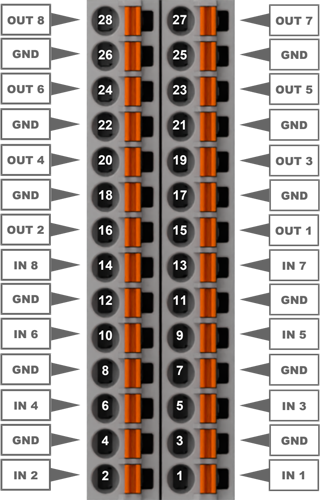
For the configuration, see Configuring RevPi MIO in the PiCtory Value Editor.
LEDs
The LEDs indicate different device statuses.
Power
| Signal | Function |
|---|---|
| Green | The connection to the RevPi base module is established. |
| Flashes red | The connection to the RevPi base module is being established (initialization phase). |
| Red | The connection to the RevPi base module is interrupted. |
OUT
| Signal | Function |
|---|---|
| Flashes red | A voltage above 10.5 V is set at one or more analog outputs. (Note: this feature is no longer supported from firmware version 1.1). |
IN
| Signal | Function |
|---|---|
| Green | One or more analog inputs are being used. |
| Flashes red | The voltage at one of the inputs exceeds the defined value of 10 V. |
Compatible Base Modules
- RevPi Connect 5
- RevPi Connect 4
- RevPi Connect SE (left side only)
- RevPi Connect+ (left side only)
- RevPi Connect S (left side only)
- RevPi Core (all variants)
See Rules for the Arrangement of Devices.
Scope of Delivery
The scope of delivery includes
- RevPi expansion module
- PiBridge connector
- X2 connector
- X4 connector
- 2 × 14-pin I/O module
- 2 × cover plug for PiBridge
Mounting and Connecting
The RevPi was developed for use in a control cabinet. Observe the specifications for the Intended Use and all Safety Instructions.
Danger to life due to electric shock
There is a risk of fatal electric shock when working on devices in the switch cabinet with 230 V mains voltage.
▷ Work in the switch cabinet may only be carried out by qualified electricians.
▷ Before carrying out any work in the switch cabinet, switch off the power supply properly.
Carry out the mounting and connection in the following order:
- Mount the RevPi base module and all expansion modules on a DIN rail.
- Connect the expansion module via the PiBridge connector.
- Connect all other devices such as sensors and actuators.
- As the last step connect the power supply.
Configuration
The RevPi expansion modules are configured via the System Configuration with PiCtory.
Configuring RevPi MIO in PiCtory
The RevPi MIO has:
- a GPIO interface with 4 identically assigned digital connections (inputs or outputs)
- 8 analog inputs for voltage
- 8 analog outputs for voltage
These can be configured in PiCtory’s Value Editor.
Mind the Pinout.
▷ Insert the RevPi MIO from the Device Catalog > I/O Devices into the correct slot in the Revolution Pi system on the Configuration Board.
▷ If necessary, adjust the basic configuration of the RevPi MIO under Device Data.
▷ Configure the settings in the Value Editor (see below).
▷ Save the configuration via File > Save as Start-Config. .
▷ Restart the driver via Tools > Reset Driver .
Connecting the System Ground (GND)
Damage to the device due to different grounding
▷ Refer all connections to the same system ground.
▷ Connect external voltage inputs or outputs with different grounding externally.
A system ground connection is available for all inputs and outputs on the 28-pin connector, which is connected through to the RevPi expansion module. All inputs and outputs refer to a common system ground as reference potential.
▷ Connect the system ground and the ground from the external voltage input (e.g. of a controller) with low impedance.
Analog Inputs
The RevPi MIO has 8 analog inputs for voltage, e.g. to connect sensors such as proximity or level sensors with analog outputs. The maximum common mode voltage per input may be between 0 and 10 V. The inputs have an overhead with a buffer of 0.76 V. Measurements above 10.76 V are blocked.
The inputs can be used in two function modes:
- analogInput: Use input for voltage measurement.
- LogicLevelInput: Use input for level detection. Switching threshold adjustable between 0 ... 10 V.
Mind the Pinout.
INP input
| Name | Value | Function |
|---|---|---|
| AnalogInputMode_1 … 8 | analogInput: for voltage measurement LogicLevelInput: for level detection | Set function mode for inputs. |
| AnalogInputLogicLevel_1 … 8 | 0: Switching threshold was not exceeded. 1: Switching threshold was exceeded. | Indicates if the switching threshold is exceeded. |
| AnalogInput_1 … 8 | 0 … 10 000 | Voltage at the input in mV. |
| InputLogicLevelVoltage_1 … 8 | 0 … 10 000 | Set switching threshold for level detection. |
| FilterWindowSize | 1 … 255 | Setting the filter width of the moving average filter. |
Moving average filter
To increase the accuracy of the AD converter, the signal is “oversampled”. The analog inputs are sampled with 15-bit resolution and are available in the process image as a millivolt value (0 to 000).
If the signal is too affected by noise, the moving average filter can be set for the analog inputs. This filter ensures that any disturbance values such as measurement noise are filtered out of your sensor’s signal.
If the moving average filter is used, the maximum frequency that can be detected decreases. The signal’s bandwidth is reduced as a result.
Analog outputs
The RevPi MIO has 8 analog outputs, e.g. to connect actuators such as frequency converters for speed control.
The outputs can be used in two function modes:
-
analogOutput: Outputs provide voltages between 0 ... 10 V.
-
LogicLevel: Outputs provide a constant, preconfigured voltage. They can be used like digital outputs. Logic level adjustable up to 10 V.
Mind the Pinout.
Damage to the device due to voltage input on the analog outputs
▷ Ensure that the pins are connected correctly.
OUT Output Values�
| Name | Value | Function |
|---|---|---|
| AnalogOutputMode_1 … 8 | analogOutput: use as analog output. LogicLevelOutput: use as digital output. | Set function mode for outputs. |
| AnalogOutput_1 … 8 | 0 … 10 000 | Set voltage in mV for output. |
| OutputLogicLevelVoltage_1 … 8 | 0 … 10 000 | Set fixed output voltage in mV for LogicLevel function mode. analogOutput must be unequal to 0 for OutputLogicLevelVoltage to be output. |
| AnalogOutputLogicLevel_1 … 8 | 0: low1: high | For LogicLevel function mode, set the outputs to high or low. |
Digital Inputs and Outputs
Das RevPi MIO besitzt 4 digitale Anschlüsse, die wahlweise als Ein- oder Ausgänge verwendet werden können.
Mind the Pinout.
You can use the digital inputs and outputs in either one of the following six operating modes.
- PWM measurement
- Pulse measurements
- Level detection
- PWM output
- Pulse output
- Level output
Notice! If you have configured an analog input as a digital input, then you can use this input only to detect the threshold value.
Using Digital Input for PWM Measurement
Frequency and duty cycle are measured in the PWM operating mode. The frequency is output in Hz and the duty cycle as a percentage with one decimal place (0999 → 0-100.0 %).
If no edge is detected for more than 10 seconds, the value 0 (No-Edge-Detected) is entered for Dutycycle and Frequency.
IO_Mode_1 = PWM Input
PWM Dutycycle_1 = Set the duty cycle here.
→ In the field Fpwm/PulseCount_1 you can then read the value that arrives at the device.
Using Digital Input for Pulse Measurement
Pulse measurements are possible up to a length of 65535 ms. It is always the measurement from the last complete pulse that is transmitted.
The physical pulse duration is also measured and the pulses counted. The period PulseLength_x is started each time a pulse is detected (rising edge).
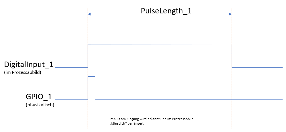
In the following example we will configure the first digital connection to use for pulse measurements. To do this you will need to set the following values in the “Value Editor” in PiCtory:
IO_Mode = PulseIn
->In the DutyCycle_PulseLength_1 field, you can read out the measured pulse length in milliseconds.
->In the Fpwm_PulseCount_1 field, you can see the number of registered pulses.
In the following example we will configure the first digital connection to use for level detection. To do this you will need to set the following values in the “Value Editor” in PiCtory:
IO_Mode_1 = Input
->In the field DigitalInput_1 you can read the level that is present at the input.
Using Digital Output for PWM Output
The four outputs are divided across 3 independent timers. GPO1 and GPO2 share a timer; GPO3 and GPO4 each have their own timer. As a result, 3 frequencies can be set. You will need to preconfigure the PWM frequency in PiCtory and restart the driver in order to adopt the changes. You can set the duty cycle (as a percentage with one decimal place) for each GPO individually (00.0).
The possible frequencies follow the formula f=(2fp)/(1000(x+1)). Here, fp is 30 MHz for GPO1&2 and 60 MHz for GPO3&4.
This results in maximum frequencies of 60 kHz (GPO1&2) and 120 kHz (GPO3&4). When x_max=65535, minimum frequencies of 1 Hz (GPO1&2) and 2 Hz (GPO3&4) are the result.
IO_Mode_1 = Output PWM.
FpwmOut_12 = Set the frequency of your PWM signal here.
PWM Dutycycle_1 = Set the duty cycle here.
Use digital output for pulse output
You can generate a pulse with a length of 1 ms to 65535 ms on each GPO.
The pulse can be generated once or regularly in retrigger mode.
One-off pulse:
If the value DigitalOutput_1 (in the process image) is set to 1, a pulse with the configured length Pulselength_1 is started. The next pulse can only be started once the current pulse is complete.
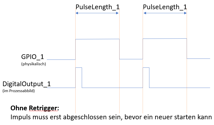
Retrigger Mode: If the value DigitalOutput_1 (in the process image) is set to 1, a pulse with the configured length Pulselength_1 is started. Current pulses can be restarted in retrigger mode.
Note: Before a new pulse can be started, the value DigitalOutput_x must be at 0 for at least one PiBridge cycle.
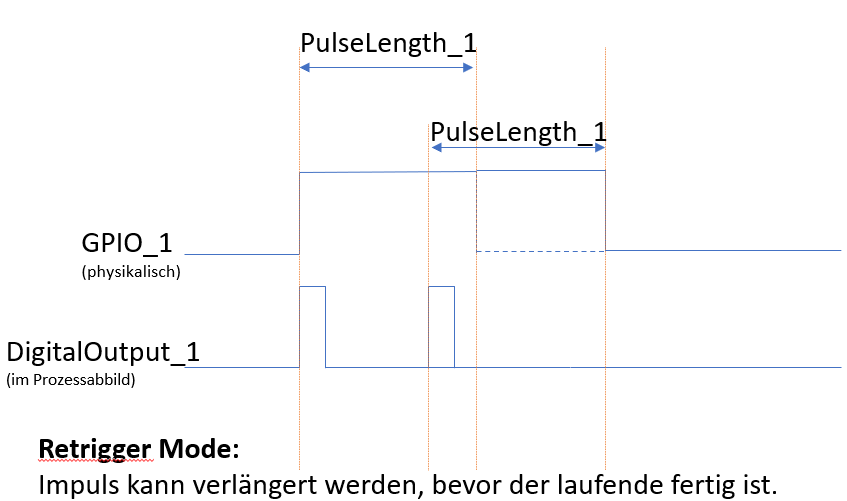
In the following example we will configure the first digital connection to use to output the pulse. To do this you will need to set the following values in the “Value Editor” in PiCtory:
IO_Mode_1 = Output Pulse
PulseMode = 1, in order to activate retrigger mode.
Dutycycle_Pulselength_1 = Set the pulse length for the connection here.
DigitalOutput_1 = 1, to start the pulse.
ATTENTION: Before you can start a new pulse, the field DigitalOutput_1 must be set to 0 for at least one PiBridge cycle.
Using Digital Output for Level Output
In the following example we will configure the first digital connection to use to output the level. To do this you will need to set the following values in the “Value Editor” in PiCtory:
IO_Mode_1 = Output
DigitalOutput_1 = Here you can set the digital output to low (0) or high (1).
List of the Setting Values for the Digital Inputs and Outputs in PiCtory
This is a summary of all the setting values for the digital inputs and outputs.
| PiCtory setting | Values | Function |
|---|---|---|
| DigitalInput_1-5 | 0: low1: high | The value indicates which level is present at the input. |
| Dutycycle_Pulselength_1-4 | 0-65535 | This value indicates the measured duty cycle or the measured pulse length, depending on which mode is set. |
| Fpwm/PulseCount_1-4 | 0-2000 | This value indicates the measured frequency or registered pulses, depending on which mode is set. |
| DigitalOutput_1-4 | 0: low1: high | Here you can set the individual digital outputs to high or low. |
| PWM Dutycycle_1-4 | 0-999 | Here you can set the duty cycle* for the individual digital outputs.*The duty cycle indicates the ratio between pulse duration and period duration for a periodic sequence of pulses. |
| Encoder Mode | 0 = No encoder 1 = Encoder on GPIO3& 4 | If you set the value 1 here, you can use GPIO3 and GPIO4 as a quad encoder input. GPIO1 and GPIO2 can continue to be used as an output with all modes or as an input (no PWM, no pulse). |
| IO_Mode_1-4 | 0 = Input Connection is used as digital output.**1 = PulseInput ** Connection is used as digital input for pulse measurement. 2 = Pwm-Input Connection is used as digital input for PWM measurement. 3 = Output Connection is used as digital output. 4 = Output-Pulse Connection is used as digital output to deliver pulses. 5 = Output-Pwm Connection is used as digital output for pulse width modulation. | Here you can define the operating mode for the respective digital input or output. |
| PulseMode | 0 = Single 1 = Retrigger | Here you can activate retrigger mode. |
| FPWMOUT_12, 3,4 | 0-65535 | 12= PWM frequency for digital outputs 1 and 2. These two connections always share the same PWM frequency. Connections 3 and 4 can be configured separately. |
| PulseLength_1-4 | 0-65535 | Pulse length on the respective digital output. |