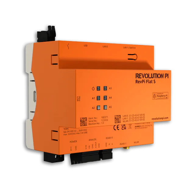
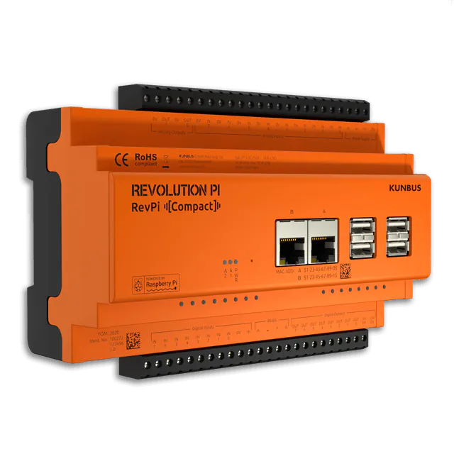
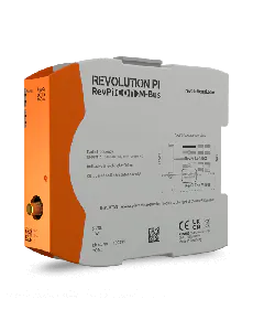
Overview RevPi Connect

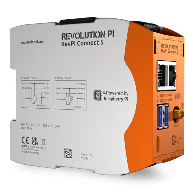
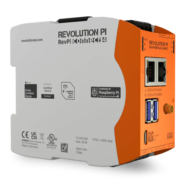
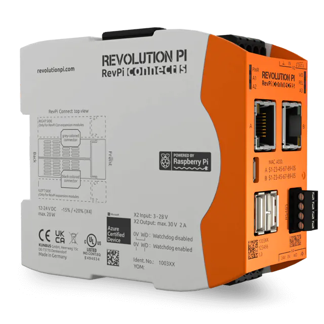
RevPi Connect has several connections that you need for your projects. Here you can find out what these are and what you can use them for.

Location Connector
1  X2 Connector

This plug has a relay contact as output and a digital input signal (+24 V). The input is connected to GND.

2 Status LEDs
The LEDs show you the status of the device. You can find out what the individual signals mean here.
3 RJ-45 sockets
You have two Ethernet ports that are independent of each other.
Tip: Use an angled plug if a small installation depth is important for you.
4 RS485 socket
Your RevPi Connect has a 4-pin RS485 socket. This allows you to connect e.g. sensors for Modbus RTU.
5 X4 Connector

This connector is responsible for the main power supply of your RevPi Connect. In addition, the watchdog is also supplied here and you can activate the watchdog here.

We deliver this plug prewired to you, so that you can start immediately. If a change is necessary, you will find a description of how to assign this plug here.

Do not connect the power supply until you have mounted your device on the DIN rail. You can operate RevPi Connect in a voltage range of 12 V-24 V.

7 USB ports

You have two USB-A ports available. This allows you to connect USB 2.0 client devices (e.g. USB hard drives, surf sticks etc.) Both sockets together may be loaded with a total of 1 A. It does not matter how the current is distributed to both sockets. For example, you can load one socket with 1 A and not use the other or load one socket with 300 A and the other with 700 A. If you need more than two USB-A ports, you will find a suitable USB hub (PR200001R00) in our shop.

8 Micro-USB connector

You can connect a USB host system here (e.g. a PC to download software to your device). While this port is connected to the USB host system, RevPi Connect switches to passive memory card mode. This allows a PC to access the built-in eMMC flash memory and store an image there, for example.

Note! Disconnect the micro-USB plug after you have played the software your RevPi Core. RevPi does not start as long as the micro-USB connector is plugged in.

Notice! Micro plugs are mechanically sensitive (you know this for sure from your mobile phone charging socket). Therefore you should never work with force and never tilt the plugs, but always insert them without much force. Never bend inserted plugs to their sides and only pull them straight out of the socket.

9 Status LED
The LEDs show you the status of the device. You can find out what the individual signals mean here.

Location Connector
1 Locking clamp

With the two locking clamps on the back of your RevPi Connect, you can securely attach your device to the DIN rail.

2 Ventilation slots

Air flows through the ventilation slots from bottom to top through the unit and cools the electronics (chimney effect).
Make sure that the ventilation slots are not covered and keep to the installation distances.

3 Connect connection
With the Connect connector you can expand your RevPi system with radio modules. Connect two modules by plugging the ConBridge connector to the ConBridge connectors of both modules.Notice! These radio modules must be connected on the right side. If you connect the modules on the left side (the PiBridge connector), your devices can be destroyed.Notice! Use the correct jumper. At this port you must use the ConBridge to connect the devices together. The devices can be destroyed if you connect them to the PiBridge.
4 Micro HDMI connector
You can use this connector to connect a monitor.
5 PiBridge Connector
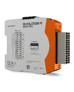
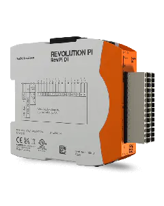
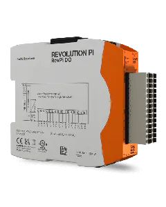
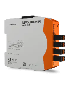
With the PiBridge connector you can connect expansion modules. Connect two modules by plugging the PiBridge connector to the PiBridge connectors of both modules. The expansion modules include:

  • RevPi DIO
  • RevPi DI
  • RevPi DO
  • RevPi AIO
  • RevPi Gate

Notice! These expansion modules must be connected on the left side. If you connect the modules on the right side (the connect port), your devices can be destroyed.

Notice! Use the correct bridge. At this connector you must use the PiBridge to connect the devices together. The devices can be destroyed if you connect them to the ConBridge.