Configuring RTD Channels for Temperature Measurements with CODESYS

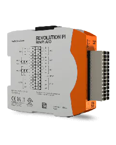
Using PiCtory, you can configure your RevPi AIO module. In this chapter, we will describe the Value Editors settings for the RTD channels in greater detail. If you are not familiar with RTD measurements, have a look at our our tutorial “basic knowledge RTD measurements“.

CODESYS helps you to configure your RevPi AIO.

  • In the CODESYS tree double-click on AIO module.
  • Navigate to the first tab “Module Parameters->Input Channels for RTD”.

Let”s go!

Your RevPi AIO has two two RTD channels. This means you can measure temperature using connected Pt100 and Pt1000 sensors.

For your configuration to work it is important that your devices are connected to the correct output pins.

Please note that the AIO module is used for a 2-wire sensor that uses the three-wire measurement system. Therefore, you basically have to simulate the missing third wire with a jumper between pins 10 and 12 and 9 and 18 respectively.

  • Open your web browser.
  • Enter the IP address of your RevPi base module in the address bar of your web browser.
    The login window opens.
  • Log in with the username “admin”.
  • Enter your password. You can find it on the sticker on the side of your base module.
  • Click on “Login”.
    You will now see the current device status of your RevPi base module.
  • Click on the “Apps” tab.
  • Click on the start button behind the entry “PiCtory”.
    PiCtory opens.
  • Open the folder “I/O Devices” in the device catalogue.
  • Select the AIO module.
  • Drag and drop the AIO in the empty slot on the configuration board.
  • Set the basic settings for your adapters in the “Device Data” window. This entry is optional. If you use a lot of devices and wish to process the data in another program later, then this entry can be very helpful.

You can configure the RTD channels in Value Editor. The detailed setting can be found in the following table:

Description

Value

Comment

RTD1Type,
RTD2Type

Pt100
Pt1000

Set here which type of measuring sensor you are using.

RTD1Wiring,
RTD2Wiring

2-Wire
3-Wire
4-Wire

Select here the measurement process that is suitable for your temperature sensor.

RTD 1 scaling
RTD1Multiplier
RTD1Divisor
RTD1Offset
RTD 2 scaling
RTD2Multiplier
RTD2Divisor
RTD2Offset

16 Bit signed Multiplier
16 Bit unsigned Divisor
16 Bit signed Offset

Set here the scaling for the RTD channels. It is determined by means of the three configuration values and calculated in accordance with the following formula from the original value (which exists in 1/10 °C):

Y = Multiplier/Divisor*X + Offset

The scaling can subsequently be used for conversion in other units or for a subsequent calibration of a temperature sensor. A 32-bit integer arithmetic is used for calculations in the AIO module. The results are then however stored as 16-bit values in the process image. Should the result Y exceed the limits of a 16-bit signed value, then the fault will be recognised and the value limited.

Example:

To have the temperature in °C without decimal places in the process image, the setting must look like this:

Multiplier = 1, Divisor = 10, Offset = 0

To have the temperature in °F in the process image, the parameter have to be set like this:

Multiplier = 18, Divisor = 100, Offset = 32

For process data in Kelvin you need these values:

Multiplier = 1, Divisor = 10, Offset = 273

  • Click on “File>Save”. This saves your file.
  • Click on “Tools>Reset Driver”. This activates the changes for the adapter.

Should an error occur, you will receive error message in the input values of the channels RTD_Status_Ch1 and RTD_Status_Ch2 located in tab AIO Module I/O Mapping. The values have the following meanings:

Bit Position

Meaning

Comment

Bit 0 (LSB)

0 = temp. is higher than -200 °C,

1 = the recorded temperature is lower than -200 °C (e.g. short circuit in sensor or cable)

Should the recorded temperature be outside the range, the respective limit will be issued (-200.0°C or 850.0°C) and the respective status bit will additionally be set.

Bit 1

0 = temp. is lower than 850 °C,

1 = the recorded temperature is higher than 850°C (e.g. a sensor isn’t connected or cable breakage).

You can establish symbolic names for the two temperature values in the channels RTD_Ch1 und RTD_Ch2 located in tab AIO Module I/O Mapping.