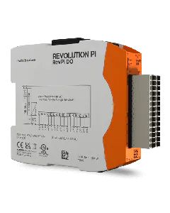
Pin Assignment

In this chapter you can find a summary of all connections and LEDs.

Power Supply

Designation

Description

24 V

10.8-28.8 V DC

0 V

Supply GND

Not assigned

Insert image FE

Functional earth

Designation

Description

24 V

10.8-28.8 V DC

0 V

Supply GND

Not assigned

Functional earth

LED

LED

Signal

Meaning

POWER

on, green

Supply is okay.

on, red

There is a problem. Check that everything is connected correctly and that your power supply unit fits correctly and is working.

OUT

flashes, red

The voltage at at least one of the outputs exceeds the defined value of 10.5 V.

IN

on, green

At least one input is used.

flashes, red

The voltage at at least one of the inputs exceeds the defined value of 10 V.

Analog Outputs

Description

Number Left

Number Right

Description

Analog output 8

28

27

Analog output 7

System GND

26

25

System GND

Analog output 4

24

23

Analog output 5

System GND

22

21

System GND

Analog output 4

20

19

Analog output 3

System GND

18

17

System GND

Analog output 2

16

15

Analog output 1

Analog Inputs

Description

Number Left

Number Right

Description

Analog input 8

14

13

Analog input 7

System GND

12

11

System GND

Analog input 6

10

9

Analog input 5

System GND

8

7

System GND

Analog input 4

6

5

Analog input 3

System GND

4

3

System GND

Analog input 2

2

1

Analog input 1

Digital Inputs and Outputs

The voltages at the GPiO connector refer to system GND.

Number

Description

1-4

All four connections are assigned identically.

Possible functions:

  • PWM input
  • PWM output
  • Pulse measurements
  • Pulse output
  • GPO 24V level output
  • GPI 24V