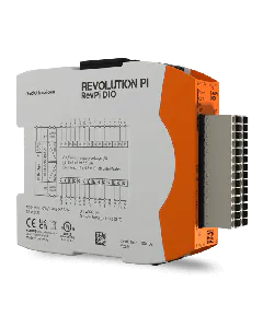
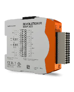
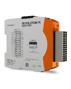
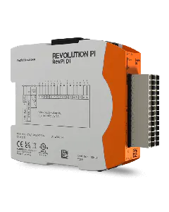
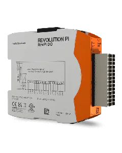
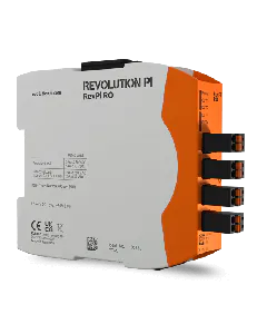
In this chapter you can find a summary of all connections and LEDs.
Power Supply
Designation | Description |
24 V | 10.8-28.8 V DC |
0 V | Supply GND |
– | Not assigned |
Insert image FE | Functional earth |

Designation | Description |
---|---|
24 V | 10.8-28.8 V DC |
0 V | Supply GND |
– | Not assigned |
Functional earth |
LED

LED | Signal | Meaning |
---|---|---|
POWER | on, green | Supply is okay. |
on, red | There is a problem. Check that everything is connected correctly and that your power supply unit fits correctly and is working. | |
OUT | flashes, red | The voltage at at least one of the outputs exceeds the defined value of 10.5 V. |
IN | on, green | At least one input is used. |
flashes, red | The voltage at at least one of the inputs exceeds the defined value of 10 V. |
Analog Outputs

Description | Number Left | Number Right | Description |
---|---|---|---|
Analog output 8 | 28 | 27 | Analog output 7 |
System GND | 26 | 25 | System GND |
Analog output 4 | 24 | 23 | Analog output 5 |
System GND | 22 | 21 | System GND |
Analog output 4 | 20 | 19 | Analog output 3 |
System GND | 18 | 17 | System GND |
Analog output 2 | 16 | 15 | Analog output 1 |
Analog Inputs

Description | Number Left | Number Right | Description |
---|---|---|---|
Analog input 8 | 14 | 13 | Analog input 7 |
System GND | 12 | 11 | System GND |
Analog input 6 | 10 | 9 | Analog input 5 |
System GND | 8 | 7 | System GND |
Analog input 4 | 6 | 5 | Analog input 3 |
System GND | 4 | 3 | System GND |
Analog input 2 | 2 | 1 | Analog input 1 |
Digital Inputs and Outputs

Number | Description |
---|---|
1-4 | All four connections are assigned identically. Possible functions:
|