PiBridge – How communication between Revolution Pi modules works

The PiBridge is the central connection element, a backplane connector, between the base module of the RevPi Core and RevPi Connect series and the RevPi expansion modules. It enables efficient and fast communication between the modules and ensures automated detection and configuration during system startup.
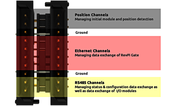
With the PiBridge, up to 10 expansion modules can be connected to a RevPi Core or RevPi Connect base module. In addition to an RS485 interface for I/O modules, the PiBridge features two Ethernet channels specifically designed for connecting RevPi gateways. This allows the Revolution Pi to be flexibly expanded and seamlessly integrated into industrial networks.
Technical Characteristics of the PiBridge
- Bus coupling of RevPi expansion modules through a 20-pin system connector
- 4 digital signal lines for controlling the initial module and position detection
- 2 signal lines for a fast RS485 data channel
- 8 signal lines for independent bidirectional 100 Mbps Ethernet data channels on both the right and left sides of the RevPi base modules

Functional Process
Startup Phase
When starting the system (or restarting the PiBridge), all connected modules are in a "waiting for configuration state". The process:
- Only the RevPi expansion module installed immediately to the right of the RevPi base module is enabled for RS485 communication and exchanges status data with the piControl driver.
- The driver recognizes the module type and compares it with the module type in a configuration file. (You must create this file beforehand with PiCtory, the graphical configuration tool.)
- If they match, the expansion module receives its specific configuration data, including a module address in the system.
- Once a module is fully recognized and configured, it enables the nearest neighboring module on its side via the control lines.
- When all modules on the right side are detected and configured, the RevPi base module continues with enabling, detecting, and configuring the left side until all modules are recognized and configured.
- Afterward, the bus termination is switched on at the respective last modules, and the cyclic RS485 communication is started with a high transmission rate.
- In parallel, the cyclic communication via the Ethernet channels is started.
Important: If the detected configuration deviates from the configuration file, piControl enters an error status, which is signaled by LED indicators.
Cyclic Data Exchange on the Ethernet Channels
The Ethernet channels of the PiBridge are currently used exclusively for the RevPi gateways to transfer up to 512 bytes of data per cycle in both input and output directions between RevPi base module and RevPi gateway. Our I/O modules are not connected to this communication channel but simply forward the channel to the next module via the PiBridge connector. Since the base module has independent Ethernet channels on both sides, one gateway can be connected per side. Exceptions include the RevPi Connect 4, RevPi Connect SE, and RevPi Core SE, where connecting RevPi gateways is not possible. For the RevPi Connect S, a gateway can only be connected on the left side.
Future expansion modules that need to use the Ethernet channels for large amounts of data can tap into a channel via an integrated Ethernet switch, thus enabling more than one module with Ethernet connection per side. Since the RevPi gateways do not have integrated switch functions and their terminating resistor on the RS485 channel is always enabled, they must always be placed at the outermost slot of the Revolution Pi system.
Cyclic Data Exchange on the RS485 Channels
Status and configuration data are transmitted on the RS485 channel during the startup phase of the system. Since it is not yet known which modules are mounted at the end of the RS485 line at this time, the bus termination is open and the transmission rate is reduced.
After completion of the startup phase, the last devices on the bus are known and receive the command to switch on the terminating resistor (exceptions are the RevPi gateways, which always have this bus termination switched on). After that, all bus participants switch the data transmission rate to the maximum value of 115.2 kbit/s and cyclically exchange the input and output data. This data exchange uses a proprietary protocol defined specifically for this purpose, optimized for small amounts of data of a few bytes per telegram.
For the experts: We have improved the ratio of payload to total length by minimizing protocol overhead.
This blog post was originally published in 2016. Technical specifications may have changed since then.


