This week we will take a closer look at our modular gateways, which can be used to connect the Revolution Pi to an industrial network such as PROFINET. In the Revolution Pi environment our modular gateways are called “RevPi Gate”.
Modular Gateways – Background Knowledge
Our gateways were developed to enable continuous and reliable communication between different industrial networks and systems (e.g. connecting a PROFIBUS network to a PROFINET network).
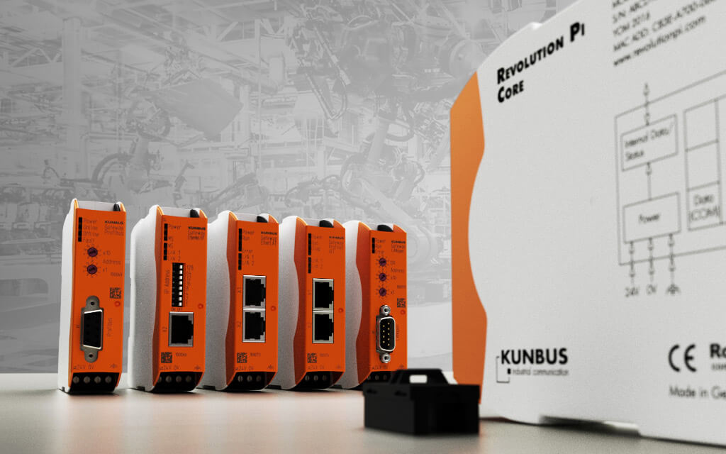
Each modular gateway consists of 2 protocol modules that master one specific protocol each. You can combine these modules as you wish. This design offers you a high degree of flexibility, since you can exchange the individual protocol modules at any time. Another advantage of the modular design is the cost factor. While common gateways have to be exchanged completely in case of a network change, the modular design of our gateways allows you to just change the module of the affected network.
Protocol modules are connected via a jumper to a gateway, using the same technique/plug, which connects the RevPi Core to the I/O modules. The size of each DIN rail module is 22.5 x 101 x 115 mm (WxHxL) and each module needs 24VDC input using heavy duty connectors at the bottom side. Reverse polarity protection prevents destruction of the module by a reversal of the polarity of the power supply.
Protocol modules (slave versions) for following industrial network protocols are currently available:
- PROFINET IRT
- EtherNet/IP
- POWERLINK
- EtherCAT
- Sercos III
- Modbus TCP
- PROFIBUS
- DeviceNet
- CANopen
- Modbus RTU
- Seriell
All module versions have been tested and certified by its respective user organizations. Protocol modules for DMX and KNX busses are currently under development.
Gateway Functionality
As mentioned before, our gateways consist of two protocol modules. Every protocol module is designed to receive and send cyclical process data from its respective fieldbus. Each protocol module has two buffer storages, each with a capacity of 512 Bytes (size depending on bus version). While one buffer storage is for writing fieldbus data, the other buffer storage is for reading fieldbus data. The two protocol modules then exchange this fieldbus data cyclically with each other. While data can be structured towards the respective fieldbus (depending on the fieldbus version), the data exchange between two protocol modules is always unstructured. It is, therefore for each fieldbus configuration to match the data structures to achieve an active protocol conversion.
Connecting RevPi Gate to RevPi Core
When using our modular gateways as RevPi Gate, the exchange of data blocks mentioned above now takes place between both storage regions of the gateway and central process image of RevPi Core. The exchange is physically handled by the Ethernet channels of PiBridge. As a result, structured data of the respective fieldbus will be applied as a block into RevPi process image or will be applied as a block to the fieldbus. By using our configurator PiCtory, this data can also be further processed in RevPi Core as structured data (for example, by soft PLC logi.RTS). The data transfer between RevPi Gate and RevPi Core runs asynchronously to all other processes (including the cyclical RevPi DIO communication). Cycle time between RevPi Core and RevPi Gate has been set by us to 5ms. Even though RevPi Gate could handle cycle time less than 2ms, the system load of the RevPi Core would be disproportionately high. The smaller the cycle time, the higher the system load of the RevPi Core used for this process.
Each RevPi Core can handle up to 2 RevPi Gate modules. The RevPi Gate modules need to be physically located at the end of each RevPi Core installation.