RS-485 waveform
Posted: 10 May 2023, 17:24
Hi all,
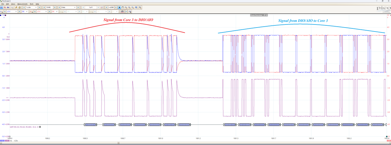
i am doing some tests and measuring the signal RS-485 on the pibridge. My devices are a revpi core 3 connected to an AIO and a DIO on the right side. I use the Picoscope series 5 to measure the signal RS-485 + (blue waveform), RS-485 - (red waveform) and difference of them (purple waveform). The picture below shows my results. As you can see, the signal from the core 3 to the device AIO or DIO looks very strange. It should be rectangular like the signal comes from AIO or DIO to Core 3, but it is not. So when I try to decode the signals with Picoscope, I get the wrong data. Can someone help me to explain it please.
Song